Norazhar Abu Bakar
580 California St., Suite 400
San Francisco, CA, 94104
The purpose of this paper was to design a much simpler control method for a wastewater treatment plant. The work proposes a direct adaptive predictive control (DAMPC) also known as subspace predictive control (SPC) as a solution to the conventional one. The adaptive control structure is based on the linear model of the process and combined with numerical algorithm for subspace state space system identification (N4SID). This N4SID plays the role of the software sensor for on-line estimation of prediction matrices and control matrices of the bioprocess, joint together with model predictive control (MPC) in order to obtain the optimal control sequence. The performances of both estimation and control algorithms are illustrated by simulation results. Stability analysis is done to investigate the response of the system proposed when parameter changes exist. This project proves that subspace-adaptive method has a large number of important and useful advantages, primarily the application ab...


![Fig. 2 World marketed energy consumption; History and Projection, 1990-2035 [7]](https://figures.academia-assets.com/66312118/figure_005.jpg)

![Fig. 3 Non-OECD energy consumption, 1990-2035 The IEO 2011 report also unveils that energy use in non-OECD Asia (led by China and India) has the most robust growth of all the non-OECD regions, rising by 117% from 2008 to 2035 (Figure 3). However, strong growth in energy use also is projected for much of the rest of the non-OECD regions. With fast-paced growth in population and access to ample domestic resources, energy demand in the Middle East increases by 77% over the projection period. Energy consumption increases by 72% in Central and South America and by 67% in Africa. The slowest projected growth among non-OECD regions is for non-OECD Europe and Eurasia, which includes Russia and the other former Soviet Republics. Growth in energy use for the region totals 16% from 2008 to 2035, as its population declines and substantial gains in Energy Efficiency (EE) are achieved through the replacement of inefficient Soviet-era capital equipment [7].](https://figures.academia-assets.com/66312118/figure_006.jpg)
![emissions are likely to be increased 35.2 billion metric tons and 43.2 billion metric tons in 2020 and 2035 respectively. These emissions are mostly occurring in developing, non-OECD nations due to relying heavily on fossil fuels especially coal mine. IEO 2011 report also reveals that non-OECD countries’ emission is likely to be total 28.9 billion metric tons in 2035, or about 73% above the 2008 level. In contrast, OECD emissions are projected total 14.3 billion metric tons in 2035-only about 6% above the level in 2008. Figure 4 depicts the emission scenario and trends of OECD and non-OECD countries from 1990-2035 [7].](https://figures.academia-assets.com/66312118/figure_007.jpg)

![Fig. 8 Production, consumption and net export of Malaysia from 1990 to 2009; oil (a) and natural gas (b) [11]](https://figures.academia-assets.com/66312118/figure_009.jpg)

![Fig. 7 Reserve of crude oil (billion barrels), natural gas (trillion feet’) and coal (billion short tons) [11]](https://figures.academia-assets.com/66312118/figure_011.jpg)
![Table 3 Percentages of coal in electricity generation [14] Proceeding of National Conference of Electric and Electronic Engineering 2012 Table 4 International crude oil and liquid fuels supply and consumption, Million bbl/d; 2007-2011 [20]](https://figures.academia-assets.com/66312118/table_005.jpg)
![Fig. 9 Fuel consumption in Malaysian power sector from 2003-2008; Unit: KTOE [21] The system capacity was 3.15kWp and is connected to a 3-phase electricity system of the building. During the same year, two further grid connected PV systems were installed by BP Malaysia and Universiti Kebangsaan Malaysia (UKM) with the capacities are 8kWp 5.5kWp respectively (currently removed). The period 2001 to 2008 covers two Malaysia Plans (the 8" and 9" MP), which inaugurates three programs such as the Small and Renewable Energy Program (SREP) program, the Biogen Full Scale Model (Biogen FSM) Demonstration Project, and the Malaysian Building Integrated Photovoltaic (MBIPV) program. The aftermath of these initiatives from 2001 to 2008 (until September) are summarized below:](https://figures.academia-assets.com/66312118/figure_012.jpg)

![Table 6 FiT Rates for Solar PV, Small Hydro, Biomass and Biogas (21 years from FiT Commencement Date) [25]](https://figures.academia-assets.com/66312118/table_007.jpg)
![Fig. 10 The second highest concrete-faced dam in the world, 2400MW hydro plant in Bakun, Sarawak; (a) - Eastward view of Crest from 2000 feet, (b) - Downstream view of Powerhouse [23] developed while the management has signed a joint venture agreement with Felda to set up a LOMW biomass plant in Jengka, Pahang.This RE plant should come on- stream by October 2012. TNB is also collaborating with Sime Darby Plantation to develop six potential biogas plants in Peninsular Malaysia with total capacity of 12MW, using palm oil mill effluent. Along with these, TNB Repair and Maintenance Sdn. Bhd. is engaged major contracts namely the Rehabilitation of Tenom Pangi hydro plant and the Operation & Maintenance (O&M) of Sandakan Power Station, 2400MW hydro plant in Bakun, Sarawak (Figure 10).](https://figures.academia-assets.com/66312118/figure_013.jpg)
![Fig. 11 Bridge illuminated with white GaN LEDs; could cut the proportion of UK electricity used for lights from 20% - 5% [28]](https://figures.academia-assets.com/66312118/figure_014.jpg)


![Where ro;, and rojp are the reflection coefficients for s-polarised and p-polarised light, respectively. 8, and 0, are the angle of incident and refraction as obtained from Snell’s law [12].](https://figures.academia-assets.com/66312118/figure_054.jpg)


![The scaling and wavelet functions are calculated by taking the inner product of the coefficients and data input values. In the last iteration, data input of s[N] and s[N+1] are not exist (they are beyond the end of the array) and cause the edge problem. To handle this edge problem, the data set is treated as it is periodic. The process of Daubechies wavelet using both scaling and wavelet functions are given as follows. Qtan 1-](https://figures.academia-assets.com/66312118/figure_060.jpg)


![Fig | Layers of the Earth’s atmosphere from the surface of the Earth [1] The Earth’s atmosphere is a thin layer of gases that surrounds the Earth. It composed of 78% of nitrogen, 21% of oxygen and 1% of other gases such as argon and carbon dioxide. This thin gaseous layer insulates the Earth from extreme temperatures; keeps heat inside the atmosphere and also blocks the Earth from the sun’s incoming ultraviolet radiation. The ionosphere, which is found from the altitude of about 60km to about 700km 1], contains up to four layers of free electrons which can enable long-distance radio communication. The Earth’s atmosphere consists of a few layers as can be seen in Figure | below.](https://figures.academia-assets.com/66312118/figure_066.jpg)
![Fig 2 Cycle 24 Sunspot Number Prediction [7]](https://figures.academia-assets.com/66312118/figure_067.jpg)


![Further, the analysis presented here includes worst case scenario to evaluate system performance. The simulation carried out is extension of the two cell model to represent MC-CDMA in time duplex mode [3]. The MC-CDMA air interface allows high-capacity networks and robustness in the case of frequency- selective channels, taking benefits from CDMA capability offered by the spread spectrum technique, and MC modulation as orthogonal frequency division multiplex (OFDM). A_ possible generic downlink transmission scheme is depicted in Fig.2. Each user data can be simultaneously processed at the spreading step before MC modulation. In the following, due to their good properties for the downlink, Walsh-Hadamard (WH) spreading sequences will be considered. The presented MC-CDMA configuration is based on the transmission of multiple data per MC-CDMA symbol for each user. Data d’; (n) denotes the ith, 1 <i < N,, data transmitted by user j, 1 <j < Ny, in the nth MC-CDMA symbol[4].](https://figures.academia-assets.com/66312118/figure_070.jpg)
![Fig.3 Transmitter schematic of MC-DS-CDMA In order to transmit high-rate data with sufficient processing gain, the chip rate of the DSCDMA system should be significantly higher than the practical limit imposed mainly by the processing speed and power consumption of state-of-the-art electronics. In this case, parallel transmissions of DS-CDMA signals using the OFDM structure can be a solution[5].](https://figures.academia-assets.com/66312118/figure_071.jpg)
![Fig.2, MC-CDMA Transmitter and Receiver Structure Obviously, MC-CDMA system offers high flexibility in resources (spectral efficiency, number of users) allocation which consequently induces large design spaces. As a result, high-level design methods are convenient in order to deal with such complexity and for efficient implementation [4].](https://figures.academia-assets.com/66312118/figure_072.jpg)
![Fig.3 shows the transmitter structure of a MC-DS-CDMA system. The N consecutive input bits of the jth user, b’;, i =0- --N~1, are serial-to-parallel converted first. Then, each bit b’; is spread by the jth user’s spreading sequence in the time domain. The other operations are identical to those of MC-CDMA. In other words, in the MC-CDMA the data bits arriving at a rate of 1/T are first spread and hence have a rate of N/T, before reducing the rate again to 1/T . By contrast, in the MC-DS-CDMaA the bit rate of R, is first reduced to R,/N and then we produce the rate R,G/N using spreading [5]. Fig. 4(a) shows the typical spectrum of the MC-DS- CDMA signal operated using the schematic of Fig.3. The subcarrier separation, fg, meets the orthogonality condition of:](https://figures.academia-assets.com/66312118/figure_073.jpg)
![of TD-SCDMA was standardized first in CCSA around the Release 5 timeframe of 3GPP, and included into Release 7 in 3GPP. The approximate relationship between the versions of TD-SCDMA released by 3GPP and CCSA is shown in Fig.5 [7]. TD-SCDMA has several different features from UMTS FDD, including a narrower bandwidth and hence lower data rate, the possibility to support asymmetric downlink/uplink (DL/UL) allocation of transmission resources, and, being a TDD system, the potential to benefit from transmit/receive channel reciprocity. Therefore, several TD-SCDMA-specific technologies have been developed to exploit these features [7]. maa. eee oe](https://figures.academia-assets.com/66312118/figure_074.jpg)


![Fig.7 General principle of MC-CDMA and MC-DS-CDMA systems indoor, and fixed and broadband wireless access (F/BWA). In addition to system-level analysis, a multitude of research activities have been addressed to develop appropriate strategies for detection, interference cancellation, channel coding, modulation, synchronization (especially uplink), and low cost implementation design[8].](https://figures.academia-assets.com/66312118/figure_076.jpg)
![Table 1 : Comparison the Performance of Three PBG Structure [2]](https://figures.academia-assets.com/66312118/table_021.jpg)
![Figure 1 : A fabricated PBG Microstrip sample and size has been proposed to analyse the performance of these materials such as periodic pattern of circular, rectangular pattern, square pattern and cross pattern. For examples, from research [2], they make an analysis with three difference periodic geometry of pattern. The geometry pattern involved are square, cross slots and a scalariform geometries. The three structures based on the same substrate and same period. A sample with a pattern arrangement of 7 x 7 elements is used as shown at Figure 1 and the result shows at Table 1. It shows the performance of the PBG structure incorporated with microstrip line with three different geometries and the scalariform cross slot geometries has a higher bandwidth.](https://figures.academia-assets.com/66312118/figure_077.jpg)


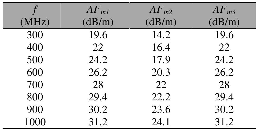
![where SAj7, SA;3, and SA>3 are site attenuations for antenna | and 2, 1 and 3, and 2 and 3 pairs respectively, while Epmax for each frequency are available in [1]. The results are given in Table 3. Antenna factors for the three antennas were calculated using the following equations:](https://figures.academia-assets.com/66312118/figure_102.jpg)


![Table 10 SAC evaluation data. NSA for OFTS and SAC were calculated using equation 2 and compared to theoretical NSA available in [2] as given in Table 11.](https://figures.academia-assets.com/66312118/table_031.jpg)


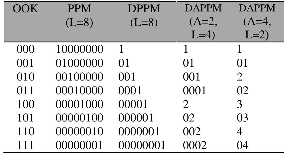
![considerations in the order of importance from optical wireless communication stand point. Fig. | Pulse modulation tree [7].](https://figures.academia-assets.com/66312118/figure_104.jpg)


![In the recent years, many algorithm and protocols about energy-efficient have been proposed. The cluster- based model is better than single-hop or multi-hop model. The cluster-based routing algorithm was proposed by [4] that optimizes the energy efficiency in WSNs. This algorithm known as Low-Energy Adaptive Clustering Hierarchy (LEACH) where the idea of this algorithm is the cluster members elect cluster head to avoid excessive energy consumption [8]. LEACH consists of 2 phases: set-up phase and steady-phase as shows in Fig. 2. In the set-up phase, sensors may elect randomly among themselves a local cluster head with a certain probability. By doing so, the network may balance energy dissipation across the whole network. The optimal number of cluster heads is 5% of the total. After the cluster heads are selected, the](https://figures.academia-assets.com/66312118/figure_114.jpg)


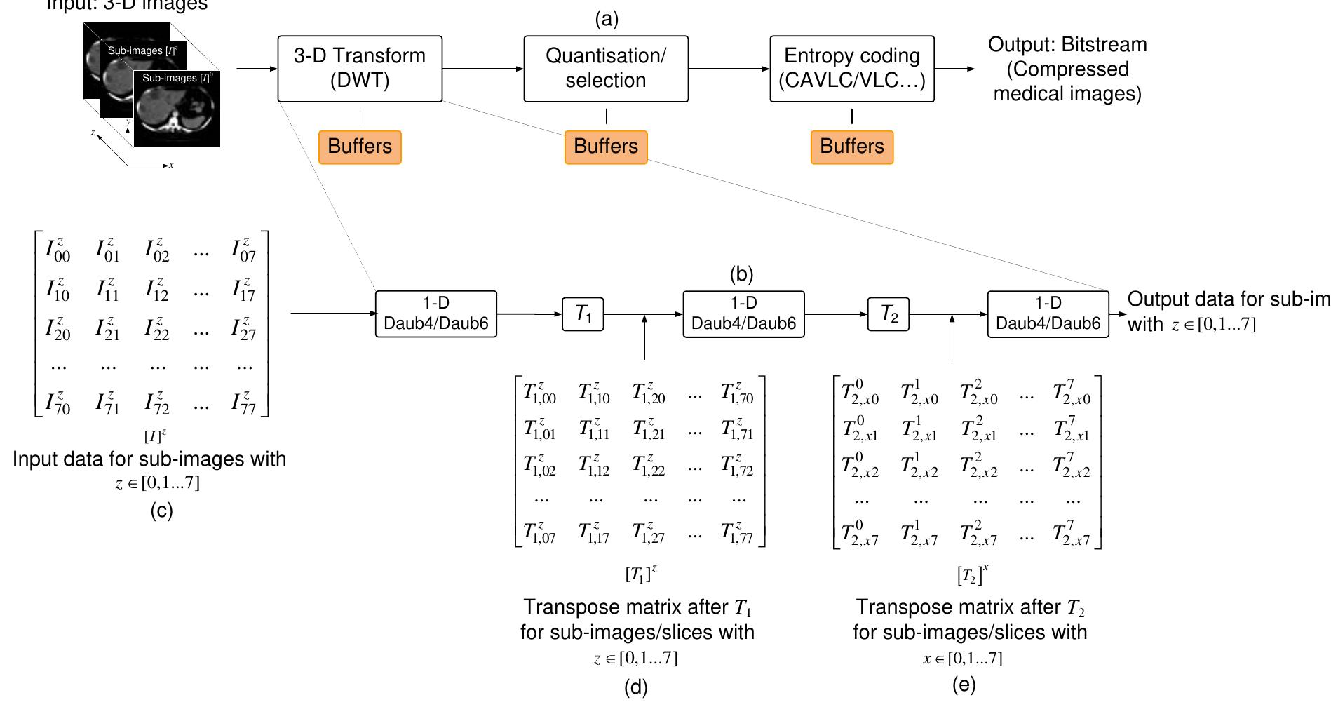
![CLALMOLTIIOOLUETE 11 A ULI? Lit UI Migital RILVILUILIIIVIIL, such as telecommunications, multimedia and integrated services digital networks, and video recordings and storage of medical images and archives fingerprints. The number of pieces that require the representation is encrypted must be less than that necessitated the original image. So that it can use less time communication or storage, and also to maintain the space in the memory unit and to facilitate the process of transferring the image from one place to another over the Internet. In the ideal image compression system includes three components as directly linked as shown in Fig 1. [4,5]. Fig 1 Signal encryption / perfect picture without losing](https://figures.academia-assets.com/66312118/figure_117.jpg)


![were between 0.2 and 0.3. Therefore, all S4 were considered as insignificant. This is in agreement with the work done in [7] and [5] where observations covering the periods from 2007 to 2009 at high latitude stations discovered that amplitude scintillations were very low during those periods.](https://figures.academia-assets.com/66312118/figure_134.jpg)
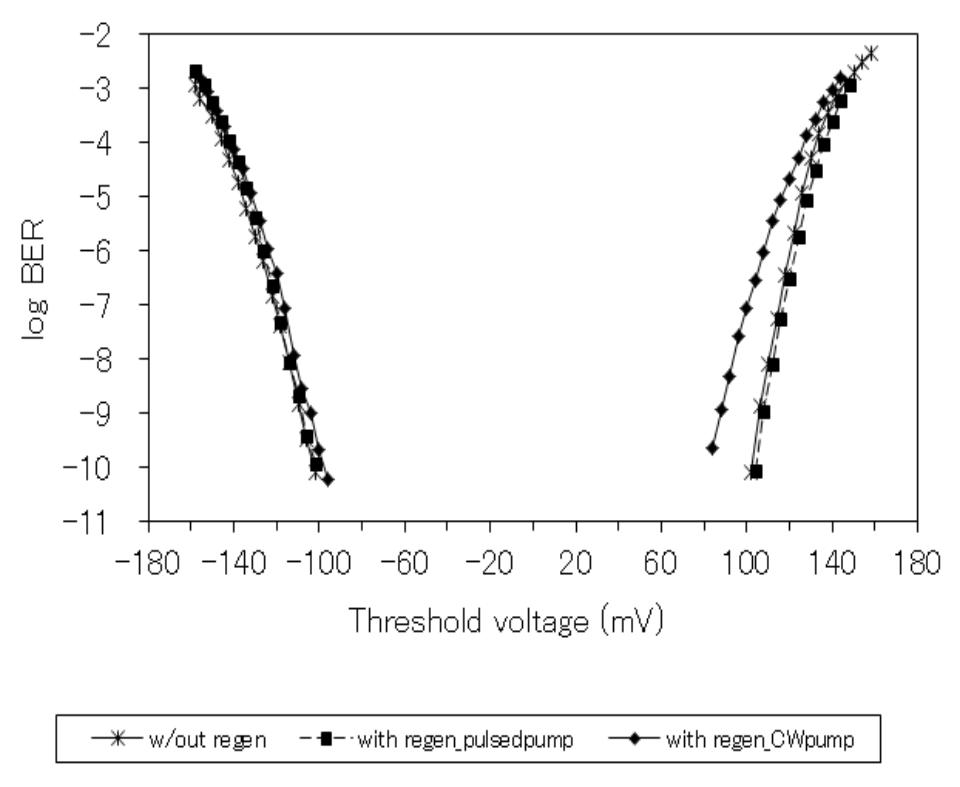
![Fig. 1 Schematic diagram of regeneration based on saturation of FWM. In this paper, we experimentally study noise suppression and addition in the regeneration based on saturation of FWM for OOK and DPSK signals. We investigate the regeneration performance when using continuous wave (CW) pump, as in [10], and pulsed pump. Signal performance is investigated by measuring BER versus threshold voltage. Progressive development in optical transmission technologies allows the growth of transmission speed and capacity. As the optical transmission system moves toward higher bit rates and more advanced technologies evolve, signal degradation becomes more dominant. Regeneration can refine the degraded signal and improve transmission performance. Conventionally, electrical repeaters are used for optical signal regenerations, which need optical-to-electrical and electrical-to-optical signal conversions. All-optical regenerator is an alternative to electrical repeater, which can work ultrafast and less complicated.](https://figures.academia-assets.com/66312118/figure_135.jpg)


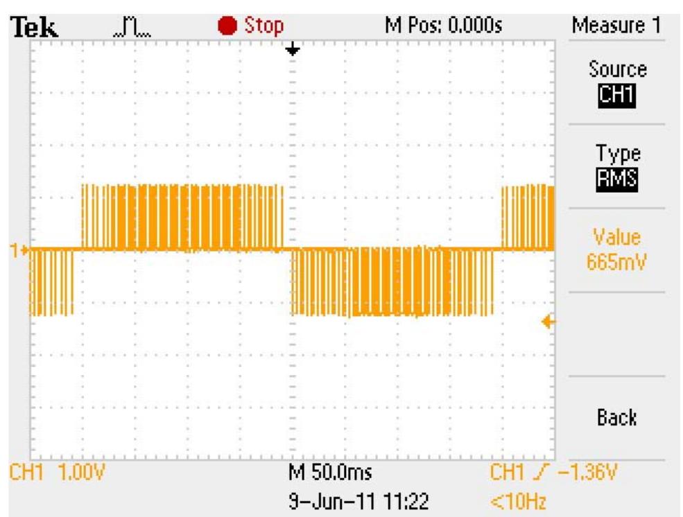
![Fig. 1 Signal waveforms of the nLVSD driver. This paper will start off with the introduction of the mLVSD driver as well as the interconnect model and associated receiver used for this work. This is followed by the comparison analyses and discussion between the diode-connected driver schemes, namely, the nLVSD, mLVSD, MJ and DDC driver schemes. It is to be acknowledged that the DDC driver is also a diode- connected driver which was analysed in [5] and compared with the MJ driver in terms of performance and power consumption in [6]. The design parameters that are to be compared are delay, power consumption and noise immunity.](https://figures.academia-assets.com/66312118/figure_139.jpg)


![Figure 2.Recycling Folded Cascode OTA [1] Fig.2 shows recycling folded cascade structure which is proposed in [1]. The input pair is split into half ( M3A, M3B, M4A, M4B) while ratio of current mirror](https://figures.academia-assets.com/66312118/figure_155.jpg)


![The ultrasonic transducers are extremely sensitive and have specific mounting requirements [3 4]. To protect the sensors from foreign matter they have been enclosed in a solid plastic container. Holes have been drilled in the container to allow pressure equalization [5].](https://figures.academia-assets.com/66312118/figure_161.jpg)
![Human body joint angle usually measured by using goniometer and lately new technique using gyroscope developed in term of better accuracy[5]. Bakshi, S. et al. (2011) compared between various techniques that previously used in human body joint angle movement measurement described in table 1 before it come out to use IMU unit which consists gyroscope and accelerometer[1].](https://figures.academia-assets.com/66312118/table_040.jpg)
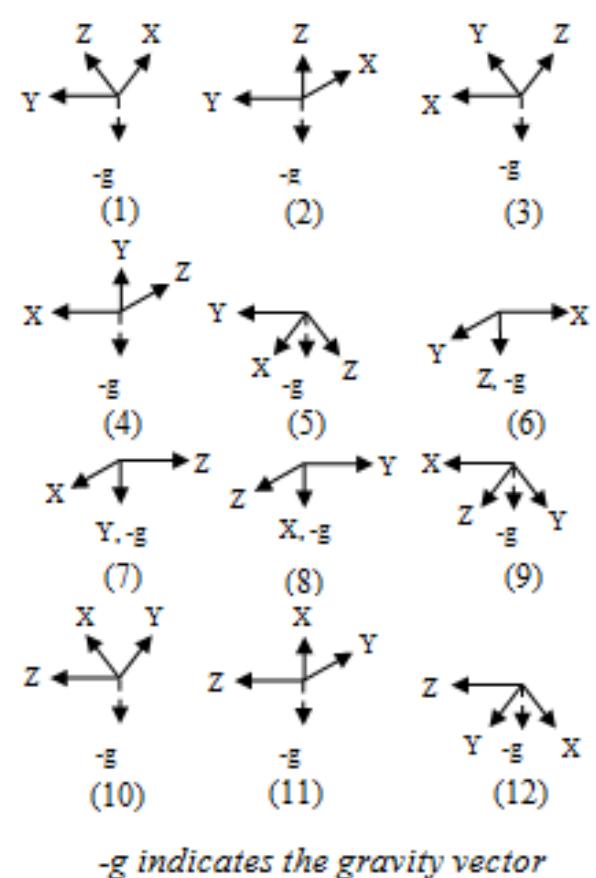
![Joint angle measured by comparing the different angle between gyroscope 2 at shank and gyroscope | at thigh. Gyroscope will produce 3 axes which z-axis as a reference axis. At the origin, angle from z-axis to x-axis and y-axis will be at 90°. While SCI patients move their leg, the angle from reference z-axis to new x-axis with y-axis as a pivot will change. This change will acknowledge as movement angle for each thigh and shank. The absolute angle measurement for each MEMS vibratory gyroscope that proposed by Friedland and Hutton in 1978 been proved by Piyabongkarn, et al. (2005) in[6]. This method is used in this project to generate angle for gyroscope 1 and gyroscope 2. SCI patients straight up their leg like in figure 2 that make orientation of gyroscope | and gyroscope 2 same and there no different in angle which mean patient do not bend their knee and there is 0° of knee bend.](https://figures.academia-assets.com/66312118/figure_162.jpg)

![Figure 3: Gyroscope Angle at Knee Bend where # is angle of knee joint, aw is angle from Z, to X, at gyroscope | at thigh and # is angle from Z, to %, at gyroscope 2. This @ and # angle get from theorem and equation in[6].](https://figures.academia-assets.com/66312118/figure_164.jpg)


![The PL spectrum of the deposited ZnO films were analysed based on PL spectra measured in room temperature. The ZnO film exhibits one recognizable UV peak at 380 nm as shown in fig. 2. The UV emission peak at 380 nm which is related to the near band edge emission is due to the excitonic recombination in ZnO [17]. Fig. 2 Room temperature PL Spectra of the deposited ZnO film.](https://figures.academia-assets.com/66312118/figure_174.jpg)


![Fig.1.Electromagnetic field on waveguide surface known as “evanescent field”. Photonics technologies as silicon-based photonics have vastly improved in the recent year mostly in optical communication and optical interconnects. [1]. Integrated photonics devices offer an important solution in improving the limitation of speed, packaging, power dissipation and sizes in microelectronic circuits/devices. [2]. One of the fundamental photonics components is waveguide and_ silicon-based photonics waveguide. Silicon based dielectric material was chosen due to integration capability with common microelectronics silicon-based technology. From literature [3], silicon on doped silicon, silicon germanium, silicon on insulator (SOD and silicon on sapphires (SOS) are first silicon- based photonics waveguides. In that four waveguide systems, silicon on insulator (SOI) become the most popular waveguide system due to SOI technology gives many advantages as lower power dissipation, high radiation tolerance and lower parasitic capacitance. Silicon on insulator (SOD, silicon nitride (SizN,4), porous silicon and silicon crystal are an examples material were used in fabrication of silicon-based waveguide. In that, In process to find surface intensity can be finds by using given equations, De nent: Anwnnitere](https://figures.academia-assets.com/66312118/figure_177.jpg)

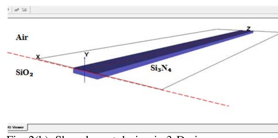
![The refractive index waveguides medium is the mair parameter here and optical input set based on core refractive index. In this studied buried Si3N, core in SiO; cladding with refractive indexs silicon _ nitride (Msi, =1-99) and silicon dioxide (Msjg, =1.46) [12] was used. In fabrication, normally SiOz cladding layer will be fabricate on silicon (Si) substrate layer but due to Si layet has a high refractive index (~3.5), SiOz cladding was used as “substrate later” in simulation methods. In traditional waveguides layers, core layer must be cladding by lower refractive index materials and OptiBPM also only possible to simulate based the rule. Fig. 2 shown Si3N, core buried into SiO2 cladding layout in OptiBPM.](https://figures.academia-assets.com/66312118/figure_179.jpg)


![generating or absorbing the reactive power at the point P [1]. The charged capacitor Cg, produces the DC output voltage Wz, to the converter which then produces a set of controllable output three phase voltages V. The voltage V is in synchronism with the AC system voltages performed by an external controller. The controller is actially performing the matching of the voltage !} with ‘;2¢ by controlling the firing angles of the converter. The voltage ¥,,¢ is set manually to the controller. The reactive current injected by the STATCOM into the systeml,, produced by the capacitor with absorbing real power from the AC system. The reactive current is as flown: Ig = — “Teg (5)](https://figures.academia-assets.com/66312118/figure_204.jpg)


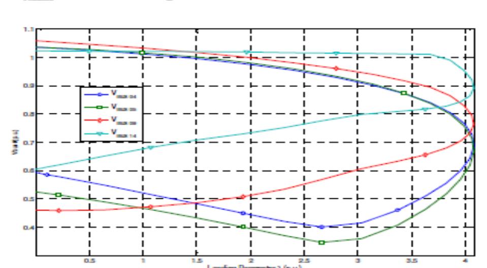
![Fig. 10. V-I Characteristics of SVC (left) and STATCOM (right) It is quite clear from the V-I characteristics in Fig. 10 that the STATCOM has more capacitive and inductive current range as compared to SVC and is capable of providing more output current than SVC. Moreover STATCOM can provide full capacitive output current at any system voltage, even current with the decreasing system voltage [2]. Additionally, it is evident that the characteristics in transient rating of the STATCOM cover greater regions of capacitive and inductive whereas the transient rating of the SVC is basically reliant on the size of the capacitor [2].also the response of STATCOM in comparison SVC is much faster because STATCOM](https://figures.academia-assets.com/66312118/figure_208.jpg)


![The power converter is an interface found between the load/generator and the grid. Depending on the topology and the applications present in the system, power can flow into the direction of both the generator and the grid. [4]. In using converters, three important things must be considered: reliability, efficiency, and cost. Fig. 2 shows a single-input single-output power converter system.](https://figures.academia-assets.com/66312118/figure_255.jpg)


![Figure 1: Phases of a three-phase system [6]](https://figures.academia-assets.com/66312118/figure_289.jpg)
![Figure 3: Phases of a six-phase system [8] Comparing the insulation clearances with the voltage (neglecting the tower width) it observe that bear no relation to each other. Thus, spatial distribution of insulation clearances do not match the voltages experience by them. Therefore, the line is not optimized to this extent.](https://figures.academia-assets.com/66312118/figure_290.jpg)
![Figure 2: Double-circuit three-phase line [7] Generally, a typical balanced three-phase system has 120° electrical degrees apart between each phase, such as shown in Figure 1. Based on this Figure 1, the relation of phase-to-phase voltage and phase-to-neutral voltage could be obtained. The phase-to-phase voltage is V3 of the phase-to-neutral voltage. In a three phase system, the three voltages with respect to ground can be written as the phasors.](https://figures.academia-assets.com/66312118/figure_291.jpg)
![In contrast with 120° phase angle of the three-phase system, a balanced six-phase system has 60° electrical degrees between each phase as shown in Figure 3. From this figure, we can obtain the relation of phase-to phase voltage and phase-to-neutral voltage for a six-phase system. Figure 4: Single-circuit six-phase line [7]](https://figures.academia-assets.com/66312118/figure_292.jpg)
![Table 1: Lightning and switching overvoltages according to IEC 60071 [12]](https://figures.academia-assets.com/66312118/table_072.jpg)
![Overvoltage types are usually classified according to their waveform shape, duration and magnitudes. Figure 5 below shows typical overvoltage magnitudes and duration [9, 10], it classifies them according to the IEC 60071-4 standard [10].](https://figures.academia-assets.com/66312118/figure_293.jpg)

![Table 6: Statutory minimum clearances to ground level [22] All aluminium alloy conductor (AAAC) type conductors have also been specified by [23] as the preferred choice for all new conductors erected on any NGC overhead line towers. Table 7 shows the standard type of AAAC conductor bundles that are typically being used on NGC’s 275 kV L3 overhead line towers [23].](https://figures.academia-assets.com/66312118/table_073.jpg)
![Table 7: Preferred AAAC type conductor bundle for NGC’s overhead line towers [23] Using the method and information presented, it is possible to initially determine the physical dimensions of an overhead line. Some formulae have been developed to calculate the clearances between the conductor bundle and nearby objects (e.g. cross-arm](https://figures.academia-assets.com/66312118/table_074.jpg)

![Figure 7: Safety distance as applied to an overhead line [11]](https://figures.academia-assets.com/66312118/figure_295.jpg)


![Fig. 1 Activated Sludge Reactor The nonlinear biological wastewater treatment process which has been studied in this paper is taken from [3]. The substances from the substrate (S), represents a source of energy and carbon (necessary for the synthesis of new cellular material) that are used by the microorganism (biomass — X) to live and reproduce](https://figures.academia-assets.com/66312118/figure_302.jpg)


![The robotics localization and mapping problem has gained researcher's attention regarding its capability to support for autonomous robot for more than two decades. It states a problem that illustrates a mobile robots observing environment and collecting information efficiently while they are moving through the environment. From the observation, robot makes estimation about the map from what it believes to be. This problem is popularly known as ‘chicken and egg' problem, and there still remains a lot of tasks to be solved even though a rapid progress have been achieved lately. Since 1990's, after a series of influential seminal papers by Smith and Cheeseman et.al[1], these research findings have directly impact to the robotic mapping research and finally has evolved its name to Simultaneous Localization and Mapping problem(SLAM). SLAM is also known as Concurrent Mapping and Localization (CML)[2]. See Figure 1 for further explanation. Fig.1 Simple SLAM illustration Nowadays, SLAM has been applied in various applications, indoor or outdoor such as satellite, mining, space exploration, rescue, and military. The development of SLAM continues whether in 2D[3Jor 3D applications[4][5][6] and has amazingly expands even to](https://figures.academia-assets.com/66312118/figure_325.jpg)


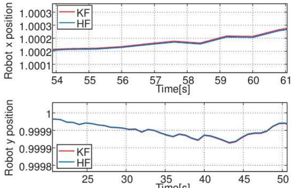


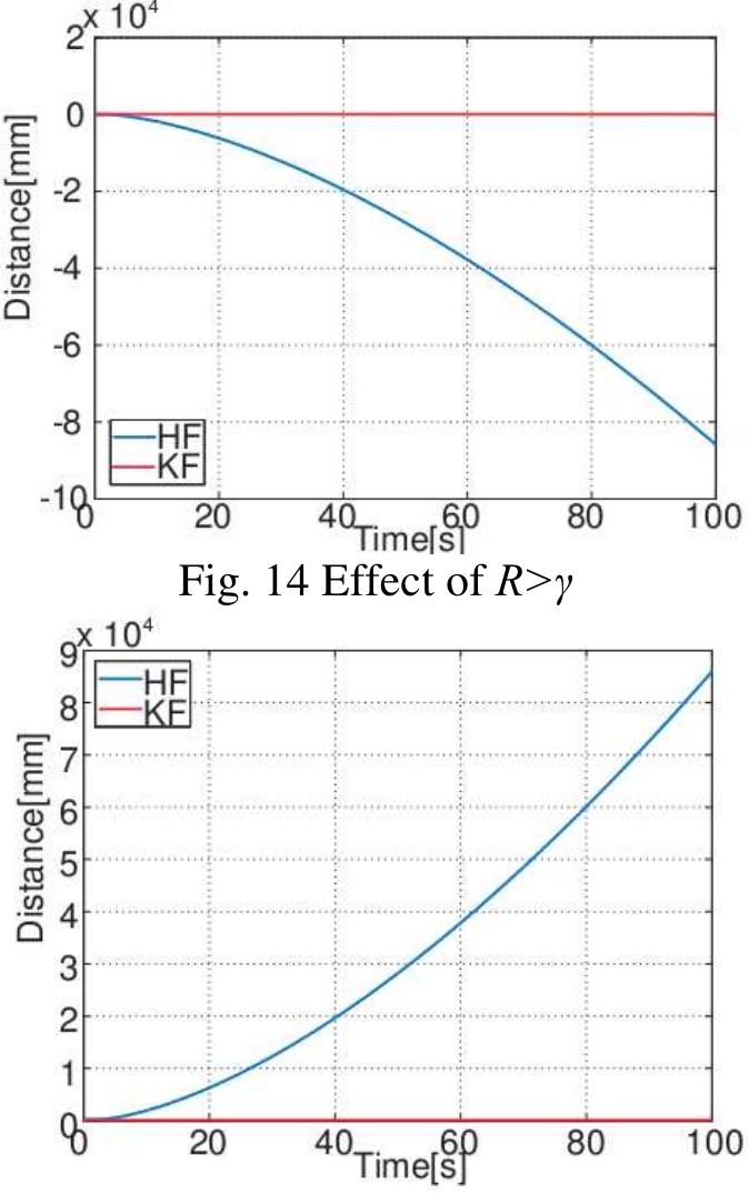
![Based on these result, it is indeed shows consistency with the results obtained previously[3] with a slight improvement from H., Filter. Belong to this results of fast convergence, process time for SLAM may reduce significantly and definitely nurture the SLAM problem. These results inspire further achievement and development of H., Filter.](https://figures.academia-assets.com/66312118/figure_339.jpg)
![Figure 1: Flowchart of the system Based on the flowchart of figure 1, development of this research starting with data gathering from experimental test by using FES for electrical stimulation test, hence pendulum test for knee joint experimental data by using Goniometer [17-19]. Data collection from anthropometric data is the data parameter of lower limb characteristic.](https://figures.academia-assets.com/66312118/figure_341.jpg)


![Figure 6: Equipment for experimental setup Due to SCI problem that illustrated in figure 5, pulse signals from brain cannot go through the human body system because of the signal have blocked. Then every level of injury base on SCI problem divided into C6,C4,T3 and L1 .In this research area, there are focused on lower limb paralysed injury of paraplegia and data will be collected during this research development study [7]. Based on the experiment from the FES architecture in figure 2, there are need some another supporting equipments during this research which is to achieve the goal in this project. Some kind of measuring meter such as Digital Multimeter and oscilloscope will be used with signal generator to generate pulse in order to compare pulses with FES (Hasomed GmbH) shown in figure 6.](https://figures.academia-assets.com/66312118/figure_345.jpg)

![Figure 7: Recumbent tricycle for spinal cord injured persons with Functional Electrical Stimulation (FES) of the paralysed muscles with motor assist [22]](https://figures.academia-assets.com/66312118/figure_347.jpg)


![Proceeding of National Conference on Electrical and Electronic Engineering 2012 Signal Representation Wavelet transform is known as a flexible approach for signal decomposition because various wavelet functions can be chosen as Mother Wavelet Function to analyze the signal [13]. Furthermore, the user can design a wavelet function if it is needed. Khezri and Jahed created a new multi-wavelet function for SEMG processing to recognize hand movements. They also used two intelligent classifiers, artificial neural network and fuzzy inference system to decrease the effect of classification technique on the accuracy of the system. Finally, a multitude of mother wavelet was selected by evaluating some wavelet such as Haar, Daubechies, coiflet, Symmlet and biorthogonal[14]. There is no rule for choosing a wavelet function in a particular application. Sometimes, more similarity between the shape of the wavelet function and the signal can be a suitable criterion for selecting the mother wavelet. But in some other is reported in [16] by studying a huge number of potential mother wavelet functions. The comparing criterion for choosing mother wavelet function was the outcome of the correlation between the signal and wavelet basis function and mother wavelet from different families had been analyzed. Eventually, the results showed that db44 from Daubechies family is the most similar function to study three biomedical signals, EMG, EEG, VPA [16].](https://figures.academia-assets.com/66312118/figure_352.jpg)
![Regarding the limitations of EMG control system, such as time delay because of huge amount of data to be processed and consequently considerable computational cost of the control system, Fuzzy Wavelet Packet (FWP) based Feature Extraction was offered by R. N. Khushaba and A. Al-Jumaily [26]. Firstly, a wavelet tree was produced by WPT through decomposition stage using a Symmlet family with four levels. Afterwards, non- distinguishing features are removed by using Fuzzy C- Mean (FCM). Next, PCA was employed for feature dimensionality reduction and lastly, a multilayer perceptron neural network classifier accomplished the classification process. Therefore, the results showed using only the first 20 principle components obtained an accuracy of 99% for six subjects. After this research, R. N. Khushaba, A. Al-Jumaily and A. Al-ani discovered another novel feature extraction method based on Fuzzy Entropy and WPT [27]. In this way, WPT with four leve of decomposition was applied on EMG signals and A combination of Wavelet theory and AI methods was reported by Y. Kocyigit and M. Korurek using WT and Fuzzy clustering Algorithm in 2001 [21]. They extracted Feature vectors by applying DWT but because of high dimension of the feature vectors, the dimensionality was reduced by employing Principle Component Analysis (PCA) method since according to K. Englehart, B. Hudgins and P.A. Parker [22], [23] applying PCA is ssential to improve WT feature extraction stage. Fuzzy ustering algorithm in [21] included Fuzzy C-Mean (FCM), Possibilitic C-Mean (PCM) and Fuzzy K-Nearest Neighbor classifier (FKNN). Eventually, a Daublet mother wavelet of order six resulted better accuracy than other wavelets with PCA, and PCM demonstrated more classification improvement in this project than FCM. Wavelet based neuro-fuzzy classification was proposed for EMG control in 2002 [8]. In this regard, DWT with Mallat algorithm was utilized and for initialization of fuzzy membership function of Neuro-Fuzzy Classifier (NFC), C-mean clustering algorithm was used and rules](https://figures.academia-assets.com/66312118/figure_353.jpg)


![Fig. 2 PID line follower algorithm travelling path One idea in controlling a line following robot is using the PID control algorithm [4]. Most importantly, PID control uses continuous function to compute the motor speeds, so that the jerkiness of the previous condition can be replaced by a smooth response. The terms of Proportional-Integral-Derivative are described as three input values used in a simple formula to compute the speed of robot either in turning left or right. The PID line follower algorithm travelling path is shown in Fig. 2.](https://figures.academia-assets.com/66312118/figure_372.jpg)