Udit Sangwan
580 California St., Suite 400
San Francisco, CA, 94104
Early version, also known as pre-print Link to publication from Aalborg University Citation for published version (APA): Schaltz, E. (2011). Electrical Vehicle Design and Modeling. In S. Soylu (Ed.), Electric Vehicles -Modelling and Simulations (1 ed., pp. 1-24). Croatia: INTECH.


![The relationship between the switching variable vector [a, b, c]t and the line-to-line output
voltage vector [Vab Vbc Vca]' and the phase (line-to-neutral) output voltage vector [Va Vb
Vc]t are given by the following relationships, where a, b, c are the orders of 51, S3, S5
respectively.
The structure of a typical three-phase VSI is shown in figure 6. As shown below, Va, Vb and
Vc are the output voltages of the inverter. S1 through S6 are the six power transistors IGBT
that shape the output, which are controlled by a, a’, b, b’, c and c’. When an upper transistor
is switched on (i.e., when a, b or c are 1), the corresponding lower transistor is switched off
(i.e., the corresponding a’, b’ or c’ is 0). The on and off states of the upper transistors, S1, Ss
and Ss, or equivalently, the state of a, b and c, are sufficient to evaluate the output voltage.](https://figures.academia-assets.com/55507705/figure_021.jpg)


![A hybrid electric vehicle is distinguee from a standard ICE driven by four different parts: a)
a device to store a large amount of electrical energy, b) an electrical machine to convert
electrical power into mechanical torque on the wheels, c) a modified ICE adapted to hybrid
electric use, d) a transmission system between the two different propulsion techniques.
Figure 1 shows the possible subsystems of a hybrid vehicle configuration [Chan, 2002],
[Ehsani, 2005]](https://figures.academia-assets.com/55507705/figure_030.jpg)
![The architecture of a hybrid vehicle is defined as the connection between the components
of the energy flow routes and control ports. Hybrid electric vehicles were classified into
two basic types: series and parallel. But presently HEVs are classified into four kinds:
series hybrid, parallel hybrid, series-parallel hybrid and complex . The primary power
source (steady power source) is made up of fuel tank and ICE and battery-electric motor
is taken as secondary source (dynamic power source).
A series hybrid drive train uses two power sources which feeds a single powerplant
‘electric motor) that propels the vehicle. In Figure 2 is shown a series hybrid electric
drive train where: fuel tank is an unidirectional energy source and the ICE coupled to an
electric generator is a unidirectional energy converter. The electric generator is connected
to an electric power bus through an electronic converter (rectifier). Electrochemical
oattery pack is the bidirectional energy source and is connected to the power bus by
means of a power electronics converter (DC/DC converter). Also the electric power bus
is connected to the controller of the electric traction motor. The traction motor can be
controlled either as a motor (when propels the vehicle) or as generator (to vehicle
oraking). A battery charger can charge batteries with the energy provided by an
electrical network.
[he possible operating modes of series hybrid electric drive trains are [Ehsani, 2005]: 1.](https://figures.academia-assets.com/55507705/figure_031.jpg)


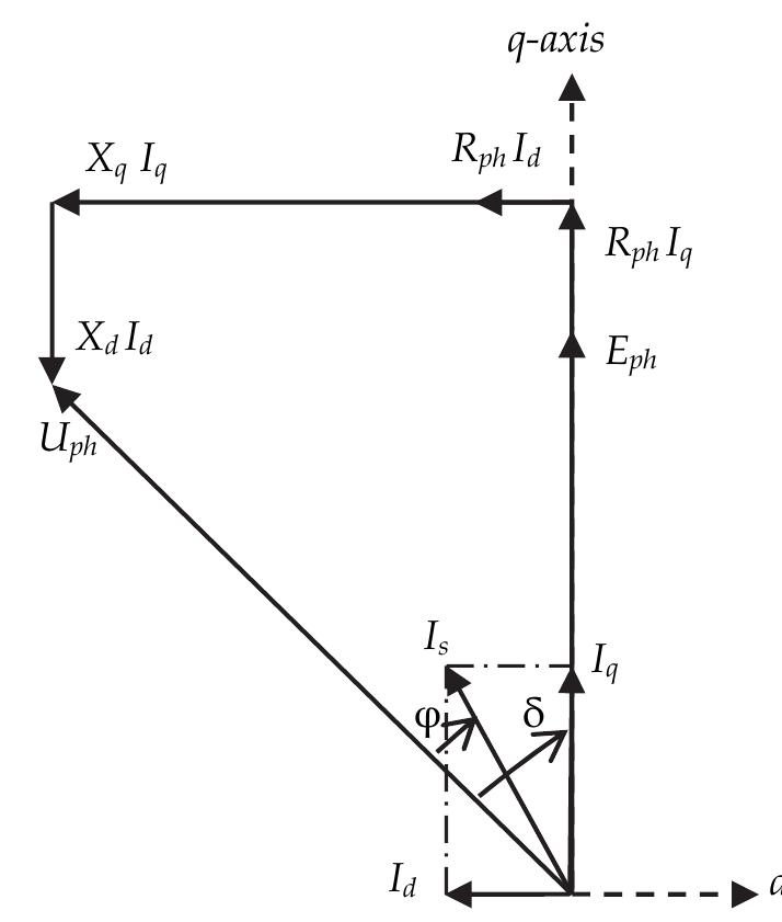
![The dynamic model of ac machine can be developed [Ehsani, 2005], [Husain, 2003], using
the concept of “space vectors”. Space vectors of three-phase variables, such as the voltage,
current, or flux, are very convenient for the analysis and control of ac motors and power
converter. A three-phase system defined by ya(t), ya(t), and yc(t) can be represented uniquely
by a rotating vector y(t) in the complex plane.](https://figures.academia-assets.com/55507705/figure_037.jpg)


![The structure of the experimental model of the hybrid vehicle is presented in Figure 11. The
model includes the two power propulsion (ICE, and the electric motor/generator M/G)
with allow the energetically optimization by implementing the real time control algorithms.
The model has no wheels and the longitudinal characteristics emulation is realized with a
corresponding load system. The ICE is a diesel F8Q of 1.91 capacity and 64[HP]. The
electronic unit control (ECU) is a Lucas DCN R04080012J-80759M. The coupling with the
motor/ generator system is assured by a clutch, a gearbox and a belt transmission.
The electric machine is a squirrel cage asynchronous machine (15kW, 380V, 30.5A, 50H:
2940 rpm) supplied by a PWM inverter implemented with IGBT modules (6KM200GB122D
The motor is supplied by 26 batteries (12V/45Ah). The hardware structure of th
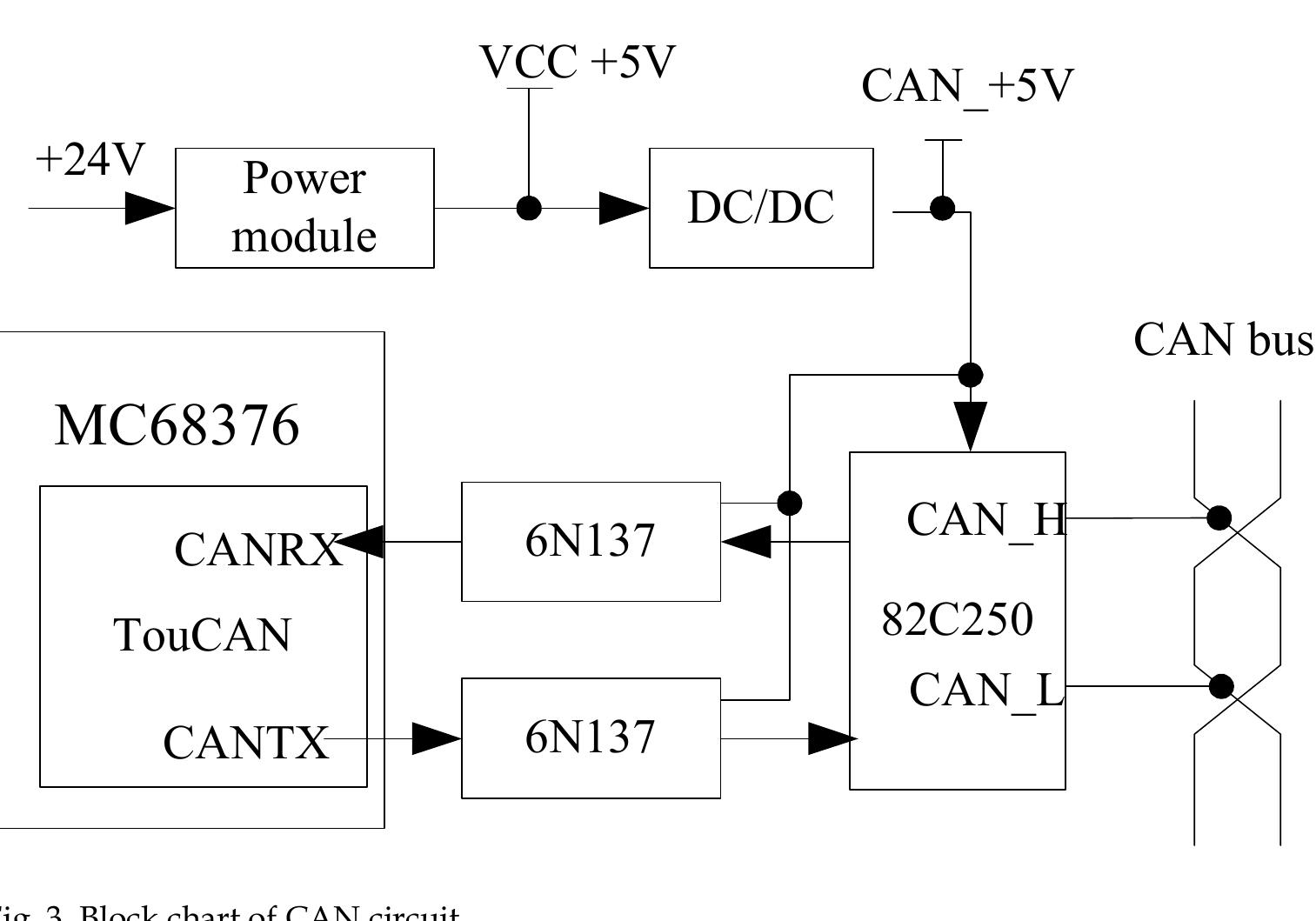
motor/ generator system is presented in Figure 12. The hardware resources assured by th
control system eZdsp 2808 permit the implementation of the local dynamic contr
algorithms and for a CAN communication network, necessary for the distributed contre
used on the hybrid electric vehicle, [Livint et all 2008, 2010]
With the peripheral elements (8 ePWM channels, 2x8 AD channels with a resolution of 1
bits, incremental transducer interface eQEP) and the specific peripheral for th](https://figures.academia-assets.com/55507705/figure_042.jpg)


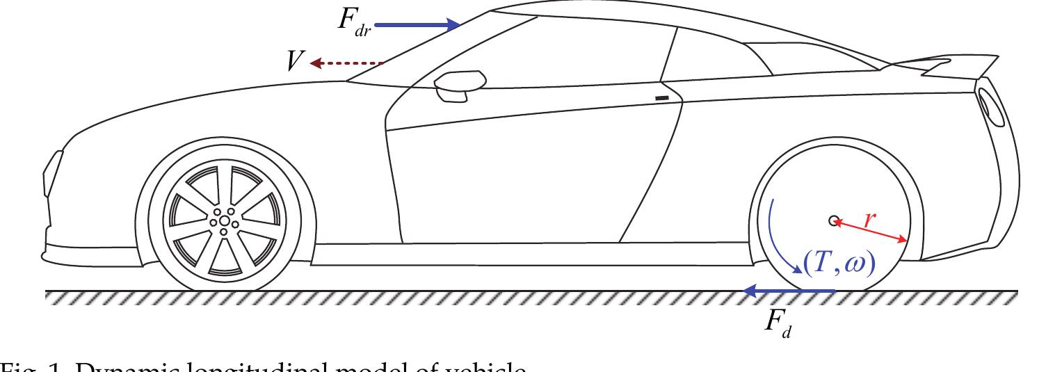
![The standard model of MFC is got under the condition that the slip ratio is set to 0. It means
that the road’s adhesion force isn’t fully utilized and the driving performance will be bad. So
this control strategy is not perfect. Secondly, MFC hasn’t good robustness to the input
signals. Especially when the angular speed is disturbed, deviation of the controller will
happen.
According to the research results from Tokyo University 5], when the tire is completely
adhered, the vehicle’s equivalent mass is equal to the sum of the sprung mass and non-
sprung mass. When the tire slips, the angular speed changes significantly. During
acceleration, the angular speed is obviously smaller than the ideal value which is outputed
by the standard model. In light of this principal, the tire’s angular speed should be
compared to the angular speed from the standard model at any time. And then the
difference is used as the basis for a correction value through a simple proportional control to
adjust the e-motor’s output torque. So that the tire can avoid slipping.
MFC strategy only requires the e-motor’s output driving torque and the tire’s angular speed
signal to put ASR into practice. Consequently the estimation of the longitudinal velocity and
the optimal slip ratio identification can be ignored. Therefore, this strategy is practical. The
te ce I a eB Ne ee ee ek](https://figures.academia-assets.com/55507705/figure_055.jpg)


![4.4 CAN Calibration Protocol (CCP)
standardization.
CCP driver is needed for ECU which parameters can be calibrated. A CCP driver software is
integrated in the infra program of HCU. A basic implementation of CCP driver needs only a
few control unit resources such as RAM, ROM, and CPU time. The CCP driver occupies two
CAN buffers, which should be assigned low bus priority to avoid influencing other bus
communication [8]. The trigger mode of CCP driver is interrupt mode. CCP driver is the
foundation of calibration platform. The calibration platform structure is shown as Fig.7. CCP
driver achieves data upload, download and calibration of controlled parameters. This
calibration system provided reliable, accurate and quickly CAN communication between
calibration platform and ECU. It has been used successfully in HEV controlled system.
The maximum bits of each flame TR can be calculated by following equation [7]](https://figures.academia-assets.com/55507705/table_041.jpg)


![Fig. 31. Power Factor Comparison
Fig. 30. Motor Power Factor
This value of , can be used to theoretically generate the rms voltage phasors V,;, V, and Vj.
using expressions (VIII), (XC) and (XCIII) in the previous chapter respectively from a
knowledge of the motor winding phasor current Jj; as per Table IV over the i/p torque
demand range range Ty 24V . The quantities obtained from BLMD simulations in Table II]
compare reasonably well with those derived in Table IV from theoretical considerations
which reinforces model validation and confidence. The optimized internal power facto1
angle, which is almost identical to that in Table III, results in a zero load angle Br from
(XCV) in the previous chapter due to the phasor collinearity and thus improved torque
control via the PWM voltage supplied by the current controlled inverter. The power facto1
angle , internal power factor angle @; and machine impedance angle @~, variations with
torque demand i/p, which are displayed in Figure 27 using estimates extracted from BLMD
model simulation in Table II] for [zy 24V, are almost congruent with a mismatched
difference manifested as the negligible load angle (B70).](https://figures.academia-assets.com/55507705/figure_353.jpg)