Introduction to
Abstract
AI
AI
The paper discusses RF power amplifiers, covering their operational frequency ranges and the various classes of amplifier topologies, including linear and nonlinear amplifications. It highlights the characteristics and applications of different amplifier classes (A, B, AB, C, D, E, F, and S) and emphasizes the importance of switching-mode amplifiers in achieving efficient signal amplification across a wide frequency spectrum.
Figures (492)
References (290)
- 3 Use of Simulation to Obtain Internal Capacitances of MOSFETs ............................................................................
- Finding C iss with PSpice .............................................
- Finding C oss and C rss with PSpice ...............................
- 4 Transient Characteristics of MOSFET ....................................
- 4.1 During Turn-On .........................................................
- 4.2 During Turn-Off .........................................................
- 5 Losses for MOSFET ................................................................
- 6 Thermal Characteristics of MOSFETs ....................................84
- 7 Safe Operating Area for MOSFETs ........................................
- 8 MOSFET Gate Threshold and Plateau Voltage ....................... References .......................................................................................... Chapter 3 Transistor Modeling and Simulation ..................................................
- 1 Introduction .............................................................................
- 2 Network Parameters ................................................................
- 2.1 Z-Impedance Parameters ...........................................
- 2.2 Y-Admittance Parameters ...........................................94
- 2.3 ABCD-Parameters ......................................................
- 2.4 h-Hybrid Parameters ..................................................96
- 3 Network Connections ............................................................ 3.3.1 MATLAB ® Implementation of Network Parameters ...111
- S-Scattering Parameters ........................................................ 3.4.1 One-Port Network ....................................................
- 4.2 N-Port Network ........................................................
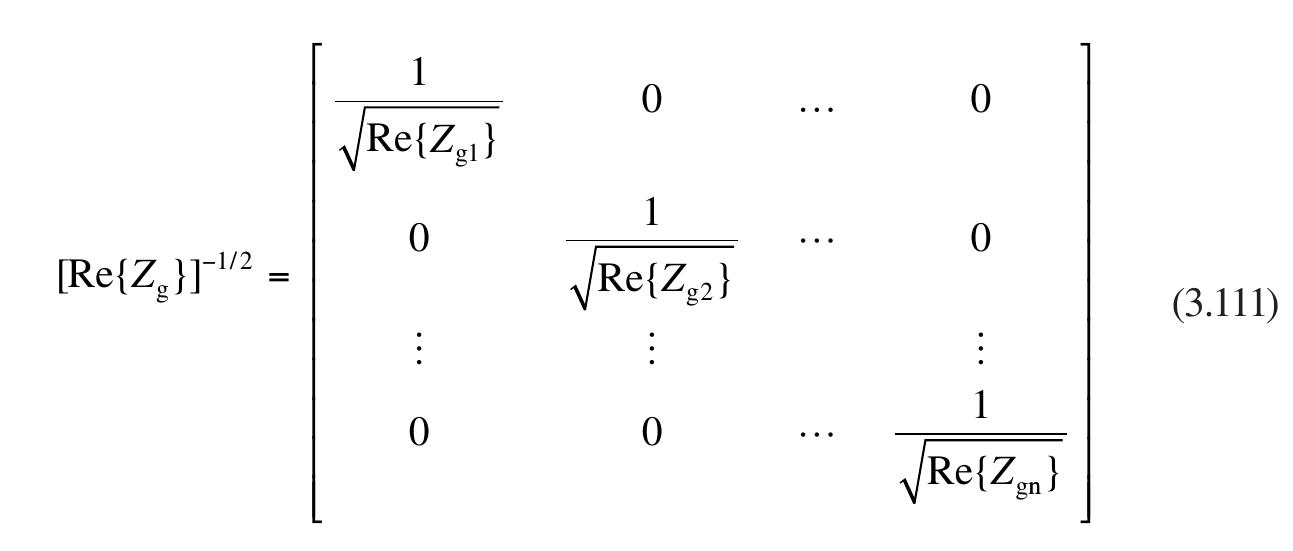
- 4.3 Normalized Scattering Parameters ..........................
- 5 Measurement of S Parameters ...............................................
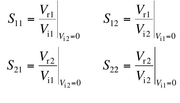
- 5.1 Measurement of S Parameters for a Two-Port Network ....................................................................
- 5.2 Measurement of S Parameters for a Three-Port Network ....................................................................
- 5.3 Design and Calibration Methods for Measurement of Transistor Scattering Parameters ...
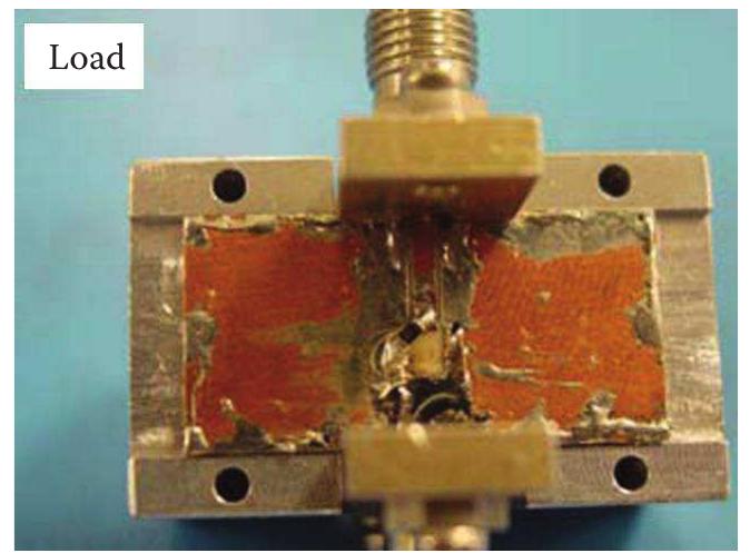
- 5.3.1 Design of SOLT Test Fixtures Using Grounded Coplanar Waveguide Structure ...
- 6 Chain Scattering Parameters .................................................
- Systematizing RF Amplifier Design by Network Analysis ...
- 8 Extraction of Parasitics for MOSFET Devices ......................
- De-Embedding Techniques ......................................
- De-Embedding Technique with Static Approach .....
- 8.3 De-Embedding Technique with Real-Time Approach ..................................................................
- References ........................................................................................ REFERENCES
- U.K. Mishra, L. Shen, T.E. Kazior, and Y.-F. Wu. 2008. GaN-based RF power devices and amplifiers. Proceedings of the IEEE, Vol. 96, No. 2, pp. 287-305, February.
- S. El Alimi, C. Münch, A. Azzi, P. Bégou, and S.B. Nasrallah. 2009. Large eddy simu- lation of a compressible flow in a locally heated square duct. International Review of Modeling and Simulations (IREMOS), Vol. 2, No. 1, pp. 93-97, February.
- O. Chocron, and H. Mangel. 2011. Models and simulations for reconfigurable magnetic- coupling thrusters technology. International Review of Modeling and Simulations (IREMOS), Vol. 4, No. 1, pp. 325-334, February.
- A. Milovanovic, B. Koprivica, and M. Bjekic. 2010. Application of the charge simu- lation method to the calculation of the characteristic parameters of printed transmis- sion lines. International Review of Electrical Engineering (IREE), Vol. 5, No. 6, Pt. A, pp. 2722-2726, December.
- M. Heidari, R. Kianinezhad, S.Gh. Seifossadat, M. Monadi, and D. Mirabbasi. 2011. Effects of distribution network unbalance voltage types with identical unbalance factor on the induction motors simulation and experimental. International Review of Electrical Engineering (IREE), Vol. 6, No. 1, Pt. A, pp. 223-228, February.
- P.H. Aaen, J.A. Pla, and C.A. Balanis. 2006. Modeling techniques suitable for CAD- based design of internal matching networks of high-power RF/microwave transistors. IEEE Transactions on Microwave Theory and Techniques, Vol. 54, No. 7, pp. 3052- 3059, July.
- R. Mittra, and V. Veremey. 2000. Computer-aided design of RF circuits. 2000 IEEE AP-S, Vol. 2, pp. 596-599, Salt Lake City.
- K.C. Gupta. 1998. Emerging trends in millimeter-wave CAD. IEEE Transactions on Microwave Theory and Techniques, Vol. 46, No. 6, pp. 747-755, June.
- R.J. Gilmore, and M.B. Steer. 1991. Nonlinear circuit analysis using the method of harmonic balance-A review of the art. Part I. Introductory concepts. International Journal of Microwave and Millimeter-Wave Computer-Aided Engineering, Vol. 1, No. 1, pp. 22-37.
- R.J. Gilmore, and M.B. Steer. 1991. Nonlinear circuit analysis using the method of harmonic balance-A review of the art. Part II. Advanced concepts. International Journal of Microwave and Millimeter-Wave Computer-Aided Engineering, Vol. 1, No. 2, pp. 159-180.
- K.S. Kundert. 1998. The Designer's Guide to Spice and Spectre. Kluwer Academic Publishers, Boston.
- B.J. Baliga. 2010. Advanced Power MOSFET Concepts. Springer, San Francisco.
- M. Deboy, N. Marz, J.-P. Stengl, H. Strack, J. Tihanyi, and H. Weber. 1998. A new gen- eration of high voltage MOSFETs breaks the limit line of silicon. IEDM '98 Electron Devices Meeting, IEDM '98, Technical Digest, pp. 683-685.
- G. Sabui, and Z.J. Shen. 2014. On the feasibility of further improving Figure of Merits (FOM) of low voltage power MOSFETs. Proceedings of the 26th International Symposium on Power Semiconductor Devices & IC's, June 15-19, Waikoloa, Hawaii.
- S. Xu et al. 2009. NexFET: A new power device. Proceedings of the International Electron Devices Meeting, pp. 1-4.
- B.J. Baliga. 1995. Power Semiconductor Devices. PWS Pub. Co, Boston.
- M.H. Rashid. 2011. Power Electronics Handbook: Devices, Circuits, and Applications. Academic Press, Burlington, MA.
- N. Mohan. 1995. Power Electronics: Converters, Applications, and Design. John Wiley and Sons, Hoboken, NJ.
- D. Graovac, M. Pürschel, and A. Kiep. 2006. MOSFET Power Losses Calculation Using the Data-Sheet Para meters. Infineon, Neubiberg, Germany. Rg=5; Cgs=10e-12;
- *pi.*f; Z3=Rds; Z4=1./(1i.*omega.*Cds)+Rhigh;
- Zp=(Z3.*Z4)./(Z3+Z4);
- %+++++++++++++++++++++++++VCCS (y-parameters)+++++++++++++++++++++++++ VCCS_11=1./(rgs.*ones(size(f))+1./(1i.*omega.*Cgs));
- %+++++++++++++++++++++++++CGD (y-parameters)++++++++++++++++++++++++++ CGD_11=
- %++++++++++++++++++++++++++RS (z-parameters)++++++++++++++++++++++++++ RS_11=RS.*ones(size(f));
- %++++++++++++++++++++++++RL (ABCD-parameters)+++++++++++++++++++++++++ RL_11=1.*ones(size(f));
- 1_mes = input('Enter S1_11 (Measured S11 in rectangular for High Frequency: ');
- 2_mes = input('Enter S1_12 (Measured S12 in rectangular for High Frequency: ');
- 1_mes = input('Enter S1_21 (Measured S21 in rectangular for High Frequency: ');
- 2_mes = input('Enter S1_22 (Measured S22 in rectangular for High Frequency: ');
- %Convert Zero Bias S parameters to Z parameters [z11,z12,z21,z22]=S2Z(s11_mes,s12_mes,s21_mes,s22_mes,Zo);
- %Extract Extrinsic Resistances using the formulation %Use Equations 3.232 through 3.234 rd=real(z21) rs=real(z22)-rd rg=real(z11)-rd %Extract Intrinsic Capacitances using the formulation %Use Equations 3.240 through 3.243 cgs=-imag(y12)/wl cgd=(imag(
- Z parameters [z11 ,z12,z21,z22]=S2Z(sc11_mes,sc12_mes,sc21_mes, sc22_ mes,Zo);
- %Extract Extrinsic Inductances using the formulation Ld=imag(z12)/wh Lg=imag(z11)/wh-Ld Ls=imag(z22)/wh-Ld %Enter Frequency range f=[1e6:500000:500e6];
- *(Lg+Ld)*1i+1i*w.*(cds+cgs)./D; Z12=rd+w.*(Ld)*1i+1i*w.*(cgs)./D; Z21=rd+w.*(Ld)*1i+1i*w.*(cgs)./D;
- s12x,s21x,s22x]=Z2S(Z11,Z12,Z21,Z22,Zo);
- smith_chart(2) for k=1:999 rd1(k)=abs(s11x(k));
- REFERENCES
- A. Eroglu. 2013. RF Circuit Design Techniques for MF-UHF Applications. CRC Press, Boca Raton, FL.
- G. Matthaei, E.M.T. Jones, and L. Young. 1980. Microwave Filters, Impedance- Matching Networks, and Coupling Structures. Artech House, Norwood, MA.
- A. Ferrero, V. Teppati, M. Garelli, and A. Neri. 2008. A novel calibration algorithm for a special class of multi-port vector network analyzers. IEEE Transactions on Microwave Theory and Techniques, Vol. 56, No. 3, pp. 693-699.
- J. Hu, K.G. Gard, and M.B. Steer. 2011. Calibrated non-linear vector network mea- surement without using a multi-harmonic generator. IET Microwaves, Antennas & Propagation, Vol. 5, No. 5, pp. 616-624, May.
- W.S. El-Deeb, M.S. Hashmi, S. Bensmida, N. Boulejfen, and F.M. Ghannouchi. 2010. Thru-less calibration algorithm and measurement system for on-wafer large-signal char- acterization of microwave devices. IET Microwaves, Antennas & Propagation, Vol. 4, No. 11, pp. 1773-1781, November.
- U. Stumper. 2005. Uncertainty of VNA S-parameter measurement due to non-ideal TRL calibration items. IEEE Transactions on Instrumentation and Measurement, Vol. 54, No. 2, pp. 676-679.
- W. Zhao, H.-B. Qin, and L. Qiang. 2012. A calibration procedure for two port VNA with three measurement channels based on T-matrix. Progress in Electromagnetics Research Letters, Vol. 29, pp. 35-42.
- I.M. Kang, S.-J. Jung, T.-H. Choi, J.-H. Jung, C. Chung, H.-S. Kim, H. Oh, H. W. Lee, G. Jo, Y.-K. Kim, H.-G. Kim, and K.-M. Choi. 2009. Five-step (pad-pad short-pad open-short-open) de-embedding method and its verification. IEEE Electron Device Letters, Vol. 30, No. 4, pp. 398-400, April.
- S. Padmanabhan, L. Dunleavy, and J.E. Daniel. 2006. Broadband space conservative on-wafer network analyzer calibrations with more complex load and thru models. IEEE Transactions on Microwave Theory and Techniques, Vol. 54, No. 9, pp. 3583-3593.
- W.M. Okamura, M.M. DuFault, and A.K. Sharma. 2000. A comprehensive millimeter- wave calibration development and verification approach. 2000 IEEE MTT-S International Microwave Symposium Digest, pp. 1477-1480, June 11-16.
- S. Rehnmark. 1974. On the calibration process of automatic network analyzer systems. IEEE Transactions on Microwave Theory and Techniques, Vol. MTT-22, pp. 457-458, April.
- J.V. Butler, D.K. Rytting, M.F. Iskander, R.D. Pollard, and M.V. Bossche. 1991. 16-term error model and calibration procedure for on-wafer network analysis measurements. IEEE Transactions on Microwave Theory and Techniques, Vol. 39, No. 12, pp. 2211- 2217, December.
- G.F. Engen, and C.A. Hoer. 1979. Thru-reflect-line: An improved technique for cali- brating the dual six-port automatic network analyzer. IEEE Transactions on Microwave Theory and Techniques, Vol. 27, No. 12, pp. 987-993, December.
- D.C. DeGroot, J.A. Jargon, and R.B. Marks. 2002. Multiline TRL revealed. 60th ARFTG Conference Digest, pp. 131-155.
- C. Shih. 1998. Advanced TRL (through-reflect-line) fixture design and error analyses for RF high power transistor characterization and automatic load pull measurement. 51st ARFTG Conference Digest, pp. 72-76.
- R.B. Marks. 1991. A multiline method of network analyzer calibration. IEEE Trans- actions on Microwave Theory and Techniques, Vol. 39, No. 7, pp. 1205-1215.
- W. Kruppa, and K.F. Sodomsky. 1971. An explicit solution for the scattering param- eters of a linear two-port measured with an imperfect test set (correspondence). IEEE Transactions on Microwave Theory and Techniques, Vol. 19, No. 1, pp. 122-123, January.
- J. Fitzpatrick. 1978. Error models for system measurements. Microwave Journal, Vol. 21, No. 5, pp. 63-66, May.
- M. Imparato, T. Weller, and L. Dunleavy. 1999. On-wafer calibration using space con- servative (SOLT) standards. 1999 IEEE MTT-S Int'l Microwave Symposium, Vol. 4, pp. 1643-1646, June.
- S. Padmanabhan, P. Kirby, J. Daniel, and L. Dunleavy. 2003. Accurate broadband on wafer SOLT calibrations with complex load and thru models. 61st ARFTG Conference Digest, June.
- B.C. Wadell. 1991. Transmission Line Design Handbook. Artech House, Norwood, MA.
- I. Wolf. 2006. Coplanar Microwave Integrated Circuits. Wiley, New York.
- Agilent Technologies. 2004. Agilent de-embedding and embedding S-parameter net- works using a vector network analyzer. Application Note 1364-1.
- M.C.A.M. Koolen, J.A.M. Geelen, and M.P.J.G. Versleijen. 1991. An improved de- embedding technique for on-wafer high-frequency characterization. Proceedings of the IEEE, Bipolar/BiCMOS Circuits and Technology Meeting, pp. 188-191, September.
- T. Hirano, J. Hirokawa, M. Ando, H. Nakano, and Y. Hirachi. 2008. De-embedding of lumped element characteristics with the aid of EM analysis. Digest of IEEE AP-S International Symposium and USNC/URSI National Radio Science Meeting, Session: 436.3, July 5-12.
- T. Hirano, H. Nakano, Y. Hirachi, J. Hirokawa, and M. Ando. 2010. De-embedding method using an electromagnetic simulator for characterization of transistors in the millimeter-wave band. IEEE Transactions on Microwave Theory and Techniques, Vol. 58, No. 10, pp. 2663-2672.
- TC1=str2double(get(handles.TC1,'String'));
- TC2=str2double(get(handles.TC2,'String'));
- Cw=str2num(get(handles.Cw,'String'));
- w=str2num(get(handles.w,'String'));
- Rsource=str2double(get(handles.Rsource,'String'));
- Rload=str2num(get(handles.Rload,'String'));
- Qp=w/Cw; C1P=Qin/(2*pi*w*RT1);
- set(handles.C1p,'String',C1P);
- XTC1=1/(2*pi*w*1i*TC1);
- XTC1; set(handles.C1,'String',c1);
- set(handles.C2,'String',c2);
- Ceq=(C1P*c2)/(C1P+c2);
- Xp=1/(2*pi*w*Ceq);
- L1=Xp/(2*pi*w);
- set(handles.L1,'String',L1);
- XCT2=1/(2*pi*w*1i*TC2);
- N=sqrt(TR2/Rload);
- LRin=(Rload*(Qp*Qp+1))/(Qout*Qout+1);
- C3=C3p-XCT2; set(handles.C3,'String',C3);
- L21=Rload/(2*pi*w*Qout);
- L22=(L21*(Qp*Qout-(Qout*Qout
- /((Qout*Qout)+1);
- L2=L22+L21; set(handles.L2,'String',L2);
- set(handles.L21,'String',L21);
- set(handles.L22,'String',L22);
- A_1=1;B_1=Rsource;C_1=0;D_1=1; ABCD_1=[A_1 B_1;C_1 D_1];
- YC1=1/(2*pi*w*c1*1i);
- YC2=1/(2*pi*w*c2*1i);
- YC22=1/YC2; YL1=(1i*L1*2*pi*w);
- ABCD_2=[A_2 B_2;C_2 D_2];
- ABCDtotal_1=ABCD_1*ABCD_2; set(handles.CA,'String',[real(ABCDtotal_1(1,1)), imag(ABCDtotal_1(1,1))].');
- set(handles.CB,'String',[real(ABCDtotal_1(1,2)), imag(ABCDtotal_1(1,2))].');
- set(handles.CC,'String',[real(ABCDtotal_1(2,1)), imag(ABCDtotal_1(2,1))].');
- set(handles.CD,'String',[real(ABCDtotal_1(2,2)), imag(ABCDtotal_1(2,2))].');
- TY11=str2double(get(handles.edit4,'String'));
- TY12=str2double(get(handles.edit5,'String'));
- TY21=str2double(get(handles.edit6,'String'));
- TY22=str2double(get(handles.edit7,'String'));
- Ytrans=(1/1000).*[TY11 TY12; TY21 TY22];
- Ydet=det(Ytrans);
- ABCDtrans=[-Ytrans(2,2)/Ytrans(2,1) -1./Ytrans(2,1);
- set(handles.TA,'String',[real(ABCDtrans(1,1)), imag(ABCDtrans(1,
- set(handles.TB,'String',[real(ABCDtrans(1,2)), imag(ABCDtrans(1,
- set(handles.TC,'String',[real(ABCDtrans(2,1)), imag(ABCDtrans(2,
- set(handles.TD,'String',[real(ABCDtrans(2,2)), imag(ABCDtrans(2,
- ImpC3=1/(2*pi*w*C3*1i);
- YL1=(2*pi*w*L22*1i);
- YL2=(2*pi*w*L21*1i);
- Series=((Rload*YL2)/(Rload+YL2))+YL1;
- Outputsimple=(Series*ImpC3)/((Series+ImpC3));
- ABCDOutput=[A B;C D];
- set(handles.LA,'String',[real(ABCDOutput(1,1)), imag(ABCDOutput(1,1))].');
- set(handles.LB,'String',[real(ABCDOutput(1,2)), imag(ABCDOutput(1,2))].');
- set(handles.LC,'String',[real(ABCDOutput(2,1)), imag(ABCDOutput(2,1))].');
- set(handles.LD,'String',[real(ABCDOutput(2,2)), imag(ABCDOutput(2,2))].');
- ABCD=ABCDtotal_1*ABCDtrans*ABCDOutput; set(handles.A,'String',[real(ABCD(1,1)), imag(ABCD(1,
- set(handles.B,'String',[real(ABCD(1,2)), imag(ABCD(1,
- set(handles.C,'String',[real(ABCD(2,1)), imag(ABCD(2,
- set(handles.D,'String',[real(ABCD(2,2)), imag(ABCD(2,
- Vg=20*log10(abs(1/ABCD(1,1)));
- set(handles.Vg,'String',Vg);
- %Frequency Response Plotting over range of Frequencies. range=[1:100000:2*w];
- for n=(1:1:V) freq=n*100000; Qp=freq/(Cw);
- A_1=1;B_1=Rsource;C_1=0;D_1=1; ABCD_1=[A_1 B_1;C_1 D_1];
- YC1=1/(2*pi*freq*c1*1i);
- YC2=1/(2*pi*freq*c2*1i);
- YC22=1/YC2; YL1=(1i*L1*2*pi*freq);
- ABCD_2=[A_2 B_2;C_2 D_2];
- ABCDtotal_1=ABCD_1*ABCD_2;
- Ytrans=(1/1000).*[TY11 TY12; TY21 TY22];
- Ydet=det(Ytrans);
- Resonator Networks for Amplifiers ABC Dtrans=[-Ytrans(2,2)/Ytrans(2,1) -1./Ytrans(2,1);
- ImpC3=1/(2*pi*freq*C3*1i);
- YL1=(2*pi*freq*L22*1i);
- YL2=(2*pi*freq*L21*1i);
- Series=((Rload*YL2)/(Rload+YL2))+YL1;
- Outputsimple=(Series*ImpC3)/((Series+ImpC3));
- ABCDOutput=[A B;C D];
- ABCD=ABCDtotal_1*ABCDtrans*ABCDOutput;
- VGdisplay window msgbox( sprintf('The required values of components are: \nC1 = %d F\ nC2 = %d F\nCm = %d F\nCa = %d F\nL1 = %d H\nL2 = %d H\n', C1,C2,Cm,Ca,L1,L2));
- %To find the frequency response, we use the ABCD parameters of the circuit %Turn the input into a T network Za1=Z_in; Zb1=1/(j*w*Ca);
- Zc1=j*w*L1; %Place into an ABCD matrix Am1=1+Za1/Zc1;
- Bm1=Za1+Zb1+Za1*Zb1/Zc1;
- Cm1=1/Zc1;
- Dm1=1+Zb1/Zc1; net1=[Am1 Bm1;
- %Transform to admittance Ya2=1/Za2;
- Yc2=1/(Zc2);
- Bm2=1/Yc2; Cm2=Ya2+Yb2+(Ya2*Yb2)/Yc2;
- Dm2=1+Ya2/Yc2; net2=[Am2 Bm2; Cm2 Dm2];
- msgbox( sprintf([... 'Calculated Parameters for Z1 \n'... ' Reflection coefficient for Z1: gamma1 =%f +j(%f)\n'... ' Reflection Coefficent for Z1 In Polar form :|gamma1|=%f,angle1=%f\n'...
- ' Standing Wave Ratio for Z1 : VSWR1=%f \n'...
- '\n'... 'Calculated Parameters for Z2 \n'... ' Reflection coefficient for Z2: gamma2 =%f +j(%f)\n'... ' Reflection Coefficent for Z2 In Polar form :|gamma2|=%f,angle1=%f\n'...
- ' Standing Wave Ratio for Z2 : VSWR2=%f \n'...
- '\n'... 'Calculated Parameters for Z3 \n'... ' Reflection coefficient for Z3: gamma3 =%f +j(%f)\n'... ' Reflection Coefficient for Z3 In Polar form :|gamma3|=%f,angle3=%f\n'...
- ' Standing Wave Ratio for Z3: VSWR3=%f \n'... '\n']... ,real(gamma1),imag(gamma1),rl1,th1*180/pi,VSWR1,real(gamma2),imag(gamma2), rl2,th2*180/pi,VSWR2,real(gamma3),imag(gamma3),rl3,th3*180/pi,VSWR3));
- When the program is executed, a GUI is displayed, as shown in Figure 5.18a, for entering impedances and the result. The results are displayed on the Smith chart in Figure 5.18b.
- A. Eroglu. 2013. RF Circuit Design Techniques for MF-UHF Applications. CRC Press, Boca Raton, FL.
- A. Eroglu, and J.K. Lee. 2008. The complete design of microstrip directional couplers using the synthesis technique. IEEE Transactions on Instrumentation and Measurement, Vol. 57, No. 12, pp. 2756-2761, December.
- G.D. Monteath. 1955. Coupled transmission lines as symmetrical directional couplers. Proceedings of the IEE-Part B: Radio and Electronic Engineering, Vol. 102, Pt. B, pp. 383-392, May.
- N.A. El-Deeb. 1983. The calibration and performance of a microstrip six-port reflec- tometer. IEEE Transactions on Microwave Theory and Techniques, Vol. MTT-31, No. 7, pp. 509-514.
- R.J. Collier, and N.A. El-Deeb. 1980. Microstrip coupler suitable for use as a six-port reflectometer. IEE Proceedings, Microwaves, Optics and Antennas, Vol. 127, No. 2, Pt. H, pp. 87-91, April.
- M. Pavlidis, and H.L. Hartnagel. 1976. The design and performance of three-line microstrip couplers. IEEE Transactions on Microwave Theory and Techniques, Vol. MTT-24, pp. 631-640.
- R.J. Collier, and N.A. El-Deeb. 1979. On the use of a microstrip three-line system as a six-port reflectometer. IEEE Transactions on Microwave Theory and Techniques, Vol. MTT-27, pp. 847-853.
- A. Eroglu, R. Goulding, P. Ryan, J. Caughman, and D. Rasmussen. 2010. Novel broadband multilayer microstrip directional couplers. 2010 IEEE AP-S, pp. 1-4, July 11-17.
- H. Park, and Y. Lee. 2010. Asymmetric coupled line directional coupler loaded with shunt inductors for directivity enhancement. Electronic Letters, Vol. 46, No. 6, pp. 425- 426, March 18.
- S. Lee, and Y. Lee. 2009. An inductor-loaded microstrip directional coupler for directiv- ity enhancement. IEEE Microwave and Wireless Components Letters, Vol. 19, No. 6, pp. 362-364, June.
- S. Lee, and Y. Lee. 2010. A design method for microstrip directional couplers loaded with shunt inductors for directivity enhancement. IEEE Transactions on Microwave Theory and Techniques, Vol. 58, No. 4, pp. 994-1002, April.
- R. Phromloungsri, V. Chamnanphrai, and M. Chongcheawchamnan. 2006. Design high- directivity parallel-coupled lines using quadrupled inductive-compensated technique. Proceedings of Asia-Pacific Microwave Conference, pp. 1380-1383.
- D. Kajfez. 1978. Raise coupler directivity with lumped compensation. Microwaves, Vol. 27, pp. 64-70, March.
- S.-M. Wang, C.-H. Chen, and C.-Y. Chang. 2003. A study of meandered microstrip coupler with high directivity. Microwave Symposium Digest, 2003 IEEE MTT-S International, Vol. 1, pp. 63-66.
- K. Sachse. 1988. Analysis of asymmetrical inhomogeneous coupled line directional coupler. Microwave Conference, pp. 985-990.
- S.L. March. 1982. Phase velocity compensation in parallel-coupled microstrip. 1982 MTT-S Int'1 Microwave Symposium Digest, pp. 410-412, May.
- A. Eroglu. 2007. Design of three-line multi-layer microstrip directional couplers at HF for high power applications. Microwave Journal, Vol. 50, pp. 150-154, April.
- J. Huang, Q. Hao, J. She, and Z. Feng. 2005. A six-port coupler with high directivity for VSWR measurement. APMC 2005 Proceedings.
- C.A. Hoer. 1972. The six-port coupler: A new approach to measuring voltage, current, power, impedance, and phase. IEEE Transactions on Instrumentation and Measurement, Vol. IM-21, No. 4, pp. 466-470.
- A.L. Cullen, S.K. Judah, and F. Nikravesh. 1980. Impedance measurement using a six- port directional coupler. IEE Proceedings, Microwaves, Optics and Antennas, Vol. 127, No. 2, Pt. H, pp. 92-98.
- T.S. Cooper, G. Baldwin, and R. Farrell. 2006. Six-port precision directional coupler. Electronics Letters, Vol. 42, No. 21, pp. 1232-1233.
- G.F. Engen, and C.A. Hoer. 1972. Application of an arbitrary six-port junction to power measurement problems. IEEE Transactions on Instrumentation and Measurement, Vol. 21, No. 4, pp. 470-474.
- G.F. Engen. 1977. The six-port reflectometer; an alternative network analyser. IEEE Transactions on Microwave Theory and Techniques, Vol. MTT-25, pp. 1075-1080.
- J.J. Yao, and S.P. Yeo. 2008. Six-port reflectometer based on modified hybrid couplers. IEEE Transactions on Microwave Theory and Techniques, Vol. 56, No. 2, pp. 493-498.
- J.J. Yao, S.P. Yeo, and M.E. Bialkowski. 2009. Modifying branch-line coupler design to enhance six-port reflectometer performance. IEEE, International Microwave Symposium, pp. 1669-1672.
- E.J. Griffin. 1982. Six-port reflectometer circuit comprising three directional couplers. Electronics Letters, Vol. 18, No. 12, pp. 491-493.
- U. Stumper. 1990. Simple millimeter-wave six-port reflectometers. IEEE Conference on Precision Electromagnetic Measurements, pp. 51-52.
- C. Akyel, and F.M. Ghannouchi. 1994. A new design for high-power six-port reflectome- ters using hybrid stripline/waveguide technology. IEEE Transactions on Instrumentation and Measurement, Vol. 43, No. 2, pp. 316-321.
- A.S.S. Mohra. 2001. Six-port reflectometer realization using two microstrip three- section couplers. 18th National Radio Science Conference, March, Egypt.
- E.R.B. Hansson, and G.P. Riblet. 1983. An ideal six-port network consisting of a matched reciprocal lossless five-port and a perfect directional coupler. IEEE Transactions on Microwave Theory and Techniques, Vol. 31, pp. 284-288.
- J.A. Dobrowolski. 1982. Improved six-port circuit for complex reflection coefficient measurements. Electronics Letters, Vol. 18, No. 17, pp. 748-750.
- F. Alessandri. 2003. A new multiple-tuned six-port Riblet-type directional coupler in rectangular waveguide. IEEE Transactions on Microwave Theory and Techniques, Vol. MTT-51, No. 5, pp. 1441-1448.
- F.M. Ghannouchi, R.G. Bosisio, and Y. Demers. 1989. Load-pull characterization method using six-port techniques. 6th IEEE Instrumentation and Measurement Technology Conference, IMTC-89, pp. 536-539.
- D. Lê, P. Poiré, and F.M. Ghannouchi. 1998. Six-port-based active source-pull measure- ment technique. Measurement Science and Technology, Vol. 9, No. 8, pp. 1336-1342.
- J. Carr. 1999. Directional couplers. RF Design, pp. 676-677, August.
- D. Kajfez. 1999. Scattering matrix of a directional coupler with ideal transformers. IEEE Microwaves, Antennas and Propagation, Vol. 146, No. 4, pp. 295-297, August.
- Micrometals. Available at http://www.micrometals.com/rfparts/rftoroid4.html.
- A. Eroglu. 2012. Complete modeling of toroidal inductors for high power RF applica- tions. IEEE Transactions on Magnetics, Vol. 48, No. 11, pp. 4526-4529, November.
- L. Shihe, and R.G. Bosisio. 1983. The measurement of complex reflection coefficient by means of a five-port reflectometer. IEEE Transactions on Microwave Theory and Techniques, Vol. 31, No. 4, pp. 321-326, April.
- L.C. Oldfield, J.P. Ide, and E.J. Griffin. 1985. A multistate reflectometer. IEEE Transactions on Instrumentation and Measurement, Vol. 34, No. 2, pp. 198-201, June.
- S.P. Yeo, and S.T. Tay. 2000. Improved design for multistate reflectometer (with two power detectors) for measuring reflection coefficients of microwave devices. IEEE Transactions on Instrumentation and Measurement, Vol. 49, No. 1, pp. 61-65, February.
- Q. Sui, K. Wang, and L. Li. 2010. The measurement of complex reflection coefficient by means of an arbitrary four-port network and a variable attenuator. 2010 International Symposium on Signals Systems and Electronics (ISSSE), Vol. 2, pp. 1-3, September 17-20.
- L. Qiao, and S.P. Yeo. 1995. Improved implementation of four-standard procedure for calibrating six-port reflectometers. IEEE Transactions on Instrumentation and Measurement, Vol. 44, No. 3, pp. 632-636, June.
- K(i)=(pi)/log(2*(1+sqrt(k2(i)))/(1-sqrt(k2(i))));
- end Cga(i)=eps0*K(i);
- Cgd(i)=((eps0*Er)/(
- *log(coth((pi/4)*sh(
- +0.65*Cf(i)* ((0.02*sqrt(Er)/sh(i))+(1-1/(Er)^2));
- Co(i)=Cp(i)+Cf(i)+Cga(i)+Cgd(i);
- %Calculation of effective permittivity constant Ce1(i)=1/((c^2)*Ce(i)*(Z0e(i))^2);
- Co1(i)=1/((c^2)*Co(i)*(Z0o(i))^2);
- epseffe(i)=Ce(i)/Ce1(i);
- /2)^2; %Calculation of length of coupler line l(i)=(c/(4*fc*sqrt(epseff(
- M,N]=size(freq);
- for k=1:1:N f=freq(M,k);
- % ABCD parameters of Each Component at each frequency Zmatrix_Ls1 = [1 (2j*pi*f*Ls1);
- Zmatrix_Ls5 = Zmatrix_Ls1;
- Zmatrix_Cs1 = [1 (-j/(2*pi*f*Cs1));
- Zmatrix_Cs5 = Zmatrix_Cs1;
- Zmatrix_Lp2 = [1 0;(-j/(2*pi*f*Lp2)) 1];
- Zmatrix_Lp4 = Zmatrix_Lp2;
- Zmatrix_Cp2 = [1 0;(2j*pi*f*Cp2) 1];
- Zmatrix_Cp4 = Zmatrix_Cp2;
- Zmatrix_Ls3 = [1 (2j*pi*f*Ls3);
- Zmatrix_Cs3 = [1 (-j/(2*pi*f*Cs3));
- % ABCD Parameter Conversion ABCD=Zmatrix_Ls1*Zmatrix_Cs1*Zmatrix_Lp2*Zmatrix_ Cp2*Zmatrix_Ls3*Zmatrix_Cs3*Zmatrix_Lp4*Zmatrix_Cp4*Zmatrix_ Ls5*Zmatrix_Cs5; A=ABCD(1,1);
- B=ABCD(1,2);
- C=ABCD(2,1);
- D=ABCD(2,2);
- S11(k)=(A+(B/Z0)-(C*Z0)-D)/(A+(B/Z0)+(C*Z0)+D);
- S21(k)=2/(A+(B/Z0)+(C*Z0)+D);
- end fprintf ('Bandpass Filter Lumped Element Component Values : \n Ls1=% 0.5e\nLs5=% 0.5e\nCs1=% 0.5e\nCs5=%... 0.5e\nLp2=% 0.5e\ nCp2=% 0.5e\nLp4=% 0.5e\nCp4=% 0.5e\nLs3=% 0.5e\nCs3=%...
- 5e\n\n',Ls1,Ls5,Cs1,Cs5,Lp2,Cp2,Lp4,Cp4,Ls3,Cs3);
- fprintf('\nInverter Values... :\nZ0J(1)=%0.4f\nZ0J(2)=%0.4f\ nZ0J(3)=%0.4f\nZ0J(4)=%0.4f\nZ0J(5)=%0.4f\nZ0J(6)=%0.4f\ n\n',... Z0J(1),Z0J(2),Z0J(3),Z0J(4),Z0J(5),Z0J(6));
- fprintf('Even-mode impedance Z0e:\nZ0e(1)= %0.4f\nZ0e(2)= %0.4f\nZ0e(3)= %0.4f \nZ0e(4)= %0.4f \n...
- = %0.4f \nZ0e(6)= %0.4f\n\n',Z0e(1),Z0e(2),Z0e(3),Z0e(4), Z0e(5),Z0e(6));
- fprintf('Odd-mode impedance Z0o:\nZ0o(1)= %0.4f\nZ0o(2)= %0.4f\nZ0o(3)= %0.4f \nZ0o(4)= %0.4f \n...
- = %0.4f \nZ0o(6)= %0.4f\n\n',Z0o(1),Z0o(2),Z0o(3),Z0o(4), Z0o(5),Z0o(6));
- fprintf ('\nEffective Dielectric Coefficient:\n');
- fprintf ('epseff(1)=% 0.4f\n epseff(2)=% 0.4f\n epseff(3)=%
- fprintf ('\nSpacing Ratio for Edge Coupled Microstrip Lines:\n') ;
- fprintf ('\nShape Ratio for Edge Coupled Microstrip Lines:\n');
- fprintf ('Electrical Length (m):\n');
- figure plot(freq*1e-9,20*log10(abs(S11)),'-mo',freq*1e- 9,20*log10(abs(S21)),'bx')
- h = legend('S_{11}(dB)','S_{21}(dB)',2);
- title('\bf{Return Loss and Insertion Loss vs Frequency(GHz)}') grid on xlabel('Frequency (GHz)') ylabel('S_{11}(dB) & S_{21}(dB)') axis([8 12 -100
- A. Eroglu. 2013. RF Circuit Design Techniques for MF-UHF Applications. CRC Press, Boca Raton, FL.
- A. Eroglu, and J.K. Lee. 2008. The complete design of microstrip directional couplers using the synthesis technique. IEEE Transactions on Microwave Theory and Techniques, Vol. 57, No. 12, pp. 2756-2761, December.
- E.J. Wilkinson. 1960. An N-way hybrid power divider. IRE Transactions on Microwave Theory and Techniques, Vol. MTT-8, pp. 116-118, January.
- A.D. Saleh. 1980. Planar electrically symmetric N-way hybrid power dividers and combiners. IEEE Transactions on Microwave Theory and Techniques, Vol. MTT-28, pp. 555-563.
- H. Howe, Jr. 1979. Simplified design of high power, N-way, in-phase power divider/ combiners. Microwave Journal, pp. 43-57, December.
- X. Tang, and K. Mouthaan. 2009. Analysis and design of compact two-way Wilkinson power dividers using coupled lines. Asia-Pacific Microwave Conference, pp. 1319-1322, Singapore.
- R. Knochel, and B. Mayer. 1990. Broadband printed circuit 0°/180° couplers and high power in phase power dividers. IEEE MTT-S International Microwave Symposium Digest, pp. 471-474.
- K.J. Russel. 1979. Microwave power combining techniques. IEEE Transactions on Microwave Theory and Techniques, Vol. MTT-27, pp. 472-478.
- A. Eroglu. 2013. RF Circuit Design Techniques for MF-UHF Applications. CRC Press, Boca Raton, FL.
- H.M. Greenhouse. 1974. Design of planar rectangular microelectronic inductors. IEEE Transactions on Parts, Hybrids and Packaging, Vol. PHP-10, pp. 101-109, June.
- A. Eroglu, and J.K. Lee. 2008. The complete design of microstrip directional couplers using the synthesis technique. IEEE Transactions on Instrumentation and Measurement, Vol. 12, pp. 2756-2761, December. FIGURE 8.29 Constructed four-die hybrid package parasitics.
- A. Eroglu. 2011. Planar inductor design for high power applications. Progress in Electromagnetic Research B, Vol. 35, pp. 53-67, December.
- A. Hamidi, N. Beck, K. Thomas, and E. Herr. 1999. Effects of current density and chip temperature distribution on lifetime of high power IGBT modules in traction work- ing conditions. Microelectronics & Reliability, Vol. 39, Nos. 6-7, pp. 1153-1158, June-July.
 Friend Name












![The nested sweep setup is When simulation is run, the I-V characteristics are obtained from the Probe interface. As seen from simulation results shown in Figure 2.12, V,,> V,,= 4.54 [V] as specified in the lib file that MOSFET conducts.](https://figures.academia-assets.com/56826516/figure_078.jpg)

















![column titled “B” in Table 3.6. The measured S$ parameters were then plotted wit the vendor-supplied spice model under the same biasing conditions, as well as th catalog vendor data for the given biases. These results are detailed in Figures 3.5 through 3.54 when V., = 1O[V] and J, = 5[{mA]. As detailed in the S parameter plots the data measured using the BFR92 test fixture aligned themselves closely with bot the vendor-supplied spice model and the vendor catalog data. The comparison of th measured and simulated data has also been done for all other conditions shown i Table 3.6. The agreement again was seen on all of them.](https://figures.academia-assets.com/56826516/table_010.jpg)





















![EEE In this section, the analysis of multistate reflectometers based on a four-port network and a variable attenuator proposed in Ref. [42] and shown in Figure 6.36 is extended to examine the more general theory of using scalar power measure- ments to determine the complex reflection coefficient. The explicit closed-form relations and solutions for the system of equations are derived and used to calculate](https://figures.academia-assets.com/56826516/figure_378.jpg)



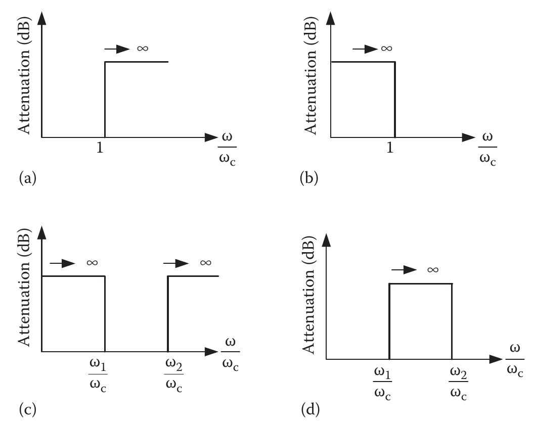
![ude ripples 1n the passband. Elliptic filters have steeper transition from passband to stopband similar Chebyshev filters and exhibit equal amplitude ripples in the passband and stopbat 2F/microwave filters and filter components can be represented using a two-pi 1etwork shown in Figure 7.3. The network analysis can be conducted using ABC yarameters for each filter. The filter elements can be considered as cascaded comfy 1ents, and hence, the overall ABCD parameter of the network is just a simple mat nultiplication of the ABCD parameter for each element. The characteristics of t ilter in practice are determined via insertion loss, S,,, and return loss, S,,. ABC yarameters can be converted to scattering parameters, and insertion loss and retu oss for the filter can be determined. The detailed analysis procedure for filters | een given in Ref. [1].](https://figures.academia-assets.com/56826516/figure_388.jpg)


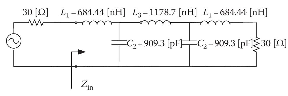
![The attenuation curves are obtained and given for several ripple values using MATLAB in Ref. [1] with examples. Example—F/2 LPF Design for RF Power Amplifiers Design an F/2 filter for an RF power amplifier that is operating at 13.56 MHz. The filter should have no impact during the normal operation of the amplifier. It should have at least 20-dB attenuation at F/2 frequency. The passband ripple should not exceed 0.1-dB ripple. It is given that the amplifier is presenting 30-Q impedance to load line. Solution](https://figures.academia-assets.com/56826516/figure_395.jpg)




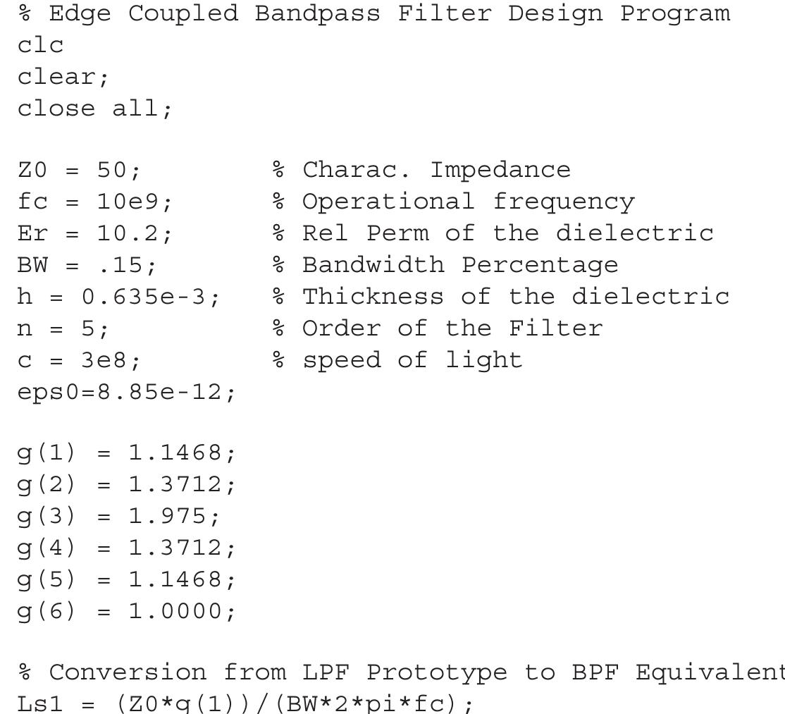
![These even- and odd-mode impedances are directly used to find the dimensions of the microstrips in the BPF. After the even- and odd-mode impedances are deter- mined, the synthesis technique introduced in Refs. [1,2] and in Chapter 6 is used to determine accurate physical dimensions. Based on the synthesis method, the spacing ratio between coupled lines is found using coupled microstrip lines. These values are also calculated in the MATLAB script from the following equations:](https://figures.academia-assets.com/56826516/figure_417.jpg)






![AMD is the arithmetic mean distance, and GMD is used for the geometric dis- tance. C is the capacitance that includes the effect of odd mode, even mode, and interline coupling capacitances between coupled lines of the spiral inductor. The detailed calculation of the capacitances is given in Ref. [9]. The substrate losses and conductor losses are ignored due to the low operational frequency. The one-port measurement network for the spiral inductor using the model pro-](https://figures.academia-assets.com/56826516/figure_447.jpg)


