 Mladenko Rak
580 California St., Suite 400
San Francisco, CA, 94104
2009
The structure consists of curved steel girders suspended over L=104 m span by means of cables system and of suspenders. The investigation of girders was conducted so that hangers were suspended from the main girder’ s medium nodes. The platforms for loads amounting from the total of 440 kN were fastened to the suspenders. The investigation was conducted throughout 5 phases. The vertical deflections, deformations (in each main cables), dynamic investigation were conducted. Results were compared for experimental and numerical investigation.


![Fig. 2: Largest pore sizes in Al-Si alloy by metallography Measurements of largest pore equivalent sizes found in a_ significant number of metallographic fields of view can be discussed in the light of the Gumbel’s distribution, [2]. An example of largest pore size data sets (i.e. Maximum Feret Diameter) entered into the Gumbel plot is shown in Fig. 2. Since each data set appreciably fulfills the linearity condition, the Gumbel statistical distribution can be used for fitting and extrapolation. The slope of the regression line is an indicator of the scatter in the data. Inspection of Fig. 2 shows that set A (modified with Na and cast in steel mold) has the largest scatter among the three materials while set B (modified with Sr and cast in steel mold) and C (modified with Sr and sand cast) have similar and reduced scatter.](https://figures.academia-assets.com/95597851/figure_006.jpg)


![Fig. 4: RLCC of Bora (load case 1) rrom recorded data 1t 1S ODV1OUS that tower response on wind load is predominantly in first vibration mode what is agreement with [3]. and the respective frequency is 0.97 Hz.](https://figures.academia-assets.com/95597851/figure_016.jpg)


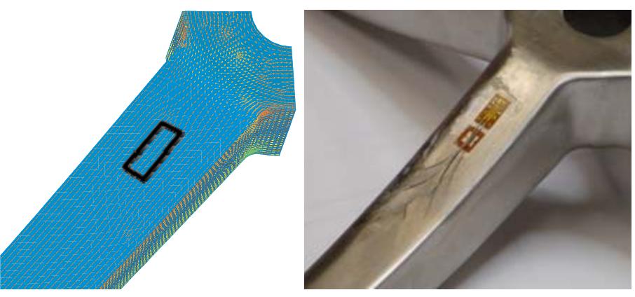
![‘ig. 1: Views of real specimen with installed FBG before and after the pressure test. Composite rotation-symmetrical elements (e.g. pressure vessels, pipes, shafts, mast, etc.) are most often fabricated from long fibers by winding technology. That method is completely automated and widespread [1-2]. The composite layers are packed in an ord programmed way in compliance with oadings. The braiding method for c ered and foreseen omposite elements manufacturing is new and a echnique in comparison with classica from 5° to 86°. Furthermore that makes possible embedding additional create so called “smart materia embedded other layers (i.e. with ternative winding method [2] and allows realization of reinforcement layer at an any angle in a range echnique elements between composite layers. It is possible to ” s” with specific magnetic properties) as well as sensors (ie. optical fiber based ones), which locally measure strain and temperature distribution composite material. Ss inside](https://figures.academia-assets.com/95597851/figure_024.jpg)
![Fig. 2: Exemplary force — strain and force — displacement curves for specimen with reinforcement angle 30° [5]. Fig. 2: Exemplary force — strain and force — displacement curves for specimen with reinforcement angle 30° [5]. During the test a compressive force (pressure), displacement of pistons as well as deformation (strain) in circumferential direction were measured. Because of large deformation on the outer surface of specimens, even few percents, Fiber Bragg Gratings (FBG) for strain measurements were used. It let to perform strain measurement very precisely in a wide range [3,4] which was not possible to obtain by classical method (electric resistance wire strain gauge).](https://figures.academia-assets.com/95597851/figure_025.jpg)
![4. References 3. Summary Fig. 3: Average values of circumferential strains for three different tube types: 30°, 45° and 60° in a function of applied load [5]. It was a result of a matrix failure in composite. So called delamination between two phases (glass fiber and epoxy resin) occurred. It was also o moment when a specimen started to whiten (see fig. 1). Maximal registered strain by FBG sensors reached 2.5% (25000 ts).](https://figures.academia-assets.com/95597851/figure_026.jpg)
![Fig. 4: Comparison of circumferential strain for tube specimen 30° [5].](https://figures.academia-assets.com/95597851/figure_027.jpg)


![Fig. 1: Specimens type, dimensions and injection gates; position of micro-CT examined samples. The effect of injection point location was analyzed both in light of fibre orientation and of the elastic properties computed by a micro- mechanical model based on the Cell Method, introduced in [4].](https://figures.academia-assets.com/95597851/figure_043.jpg)


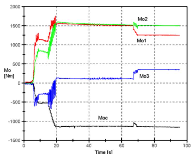
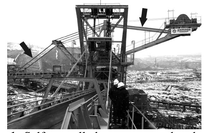
![There are often applied machines in the min- ing of the lignite coal about the long operating period frequently reaching 50 years [2]. There- fore the analyses of the state of these machines are being conducted in order to determine the alternative of their exploitation or replacing it by new. One of examinations conducted at this occasion there are measurements of oscillation and dynamic influences during mining [1]. These examinations are aimed at determining real dynamic loading and the scope of changes of stresses which can be a base for determining the fatigue life of elements of the load-carrying system [3]. Linking experimental methods with numerical methods it is possible on the basis of measurements in selected points to appoint the state of stresses and deformations in the entire load-carrying system. Fig. 1: View of RS-560 chain excavator](https://figures.academia-assets.com/95597851/figure_050.jpg)


![The influence of measured dynamic loads on the load-carrying structure of the excavator was determined with the help of computer simula- tions. A FEM shell-beam model was built [4, 5] in I-DEAS NX software shown on fig. 5. Fig. 5: FEM model of load-carrying structure of excavator](https://figures.academia-assets.com/95597851/figure_053.jpg)


![Fig. 1: Isometric view of testing facility. It is equipped by twenty-one hydraulic actuators. A real time control system guarantee synchronous application of each kind of load history on bogie frame. Here, a set of ad hoc fittings and twenty-one actuators guarantee load application, on each direction, on wheels, with the superposition of twist [2]. The same apply](https://figures.academia-assets.com/95597851/figure_064.jpg)


![3. Results In straight and curved = glued laminated timbers (glulam) residual stresses can be significant due to change of climatic conditions. The stress caused by the manufacturing process, the load and the climatic conditions add together. The resulting stress may cause failure. We can find them in practice when the lamellas break or crack parallel to the fibre direction. Our research team uses a stress evaluation method developed at the University of West Hungary [1]. If we know the geometry of the glulam structure, the properties of the lamellas -the thickness, Young’s modulus, the climatic and the manufacturing residual stress can be determined. We also need the initial and final temperature and _ the moisture content values of the lamellas to calculate the climate residual stresses.](https://figures.academia-assets.com/95597851/figure_078.jpg)


![Fig. 1: Image correlation principle [2] The Q400 measuring system is very easy to handle. Before any measurement the system calibration is necessary to be performed. The Q-400 system has, for a _ successful measurement, a _ calibration procedure incorporated in the measurement and analysis software ISTRA-4D. By the calibration procedure are determined the intrinsic and extrinsic parameters of the cameras. A test plate with a chess model on it is moved in front of the cameras.](https://figures.academia-assets.com/95597851/figure_081.jpg)
![Fig. 2: Experimental set-up The tensile test was conducted according to the EN 10002-1:1990 European Standard for tensile testing of metallic materials at ambient temperature [4]. Five specimens having the same dimensions were tested in the same conditions to check if the measuring results can be reproduced. Instead of using a classical extensometer during the tensile test many images of the specimen were acquired by both cameras of the optical measurement system. The values of the corresponding force at the acquisition time were recorded.](https://figures.academia-assets.com/95597851/figure_082.jpg)


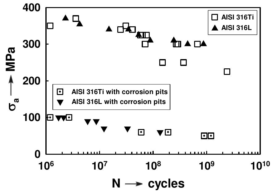
![Fig. 1: The fatigue test bar Beside the reference S-N curve, taken for air, three more S-N curves were obtained. They are referred to (1) acidic solution: 50g NaCl + 5g CH;COOH + 945g H,O with pH = 2.7 — 3.0; (11) alkaline solution: 1N water solution Na,CO; and NaHCO, with the ratio 1:1 according to AGA [2] and pH = 9.3; and (iii) water from water main with pH = 6.5. For fatigue tests flat bars (Fig.1) were used.](https://figures.academia-assets.com/95597851/figure_113.jpg)


![Several triangulating laser measuring probes (triangulation methods) by Festo are used for length measuring systems [1]. Fig. 2: Measuring bridge with the measuring olatform and five mounted laser triangulation sensors](https://figures.academia-assets.com/95597851/figure_136.jpg)
![Fig. 1: Telescopic cover - Direction of wiper friction and resistance forces (F, and F,) Machine tool manufacturers begin to focus on optimizing peripherals such as telescopic covers [1]. Passive resistance of covers and its sealing wipers in particular becomes more significant factor of drive power dimensioning. 2. Sealing wiper](https://figures.academia-assets.com/95597851/figure_137.jpg)
![Fig. 2: Comparison of experimental and modelled stiffness characteristics Physical behaviour of sealing wiper ha been examined by a mathematical model and ; has been verified by an experiment [2]. It stiffness characteristic is bilinear respecting tw contact zones of the wiper (compliant wiper li and stiffer sealing plane).](https://figures.academia-assets.com/95597851/figure_138.jpg)

![Fig. 6: Normal force curve along wiper length; all wipers in contact with segments This model also shows whether the wiper is in contact with the segment below to assure sealing functionality. If the normal force of any segment reaches zero, it means that there is no preload of wiper. Zero preload represents gap between wiper and the segment. This can happen in case of large cover and it must be prevented by cover modification [3].](https://figures.academia-assets.com/95597851/figure_140.jpg)


![Wood exhibits a hierarchical structure and is composed of fibers which can be represented as hollow tubes oriented in stem direction (see Fig. 1(a)). The fibers are built up of a cell wall material consisting of stiff cellulose microfibrils which are embedded in a soft polymer matrix. The S2 layer of the cell wall occupies approximately 80 % of the cell wall and mainly contributes to the load bearing capacity of wood. Within the S2 layer, the stiff microfibrils are inclined to the longitudinal cell axis by the so. called mircofibril angle, giving an approximately transversely isotropic material. Fig. 1: (a) Wood fiber consisting of different cell wall layers and (b) conical indentation in S2 layer of wood cell wall: orientation of the material axis and indentation direction. The mechanical properties of the S2 layer can be measured by tension tests on single wood fibers or by means of nanoindentation. As reported by several authors (see, e.g., [1]), the measured indentation modulus in longitudinal direction is considerably smaller than the expected Young’s modulus in the same direction. This can be explained by the small](https://figures.academia-assets.com/95597851/figure_154.jpg)

![Fig. 2: Comparison of predicted and measured [6] indentation modulus.](https://figures.academia-assets.com/95597851/figure_156.jpg)
![Flexible polyurethane foams are commonly used materials in automotive applications, especially for internal cockpit parts and seats. During accidental impact passenger’s head has to be stopped by the headrest (Fig.1). As it is showed in Fig.2, padding material of a headrest has a_ significant influence on a_ head deceleration [3]. Mechanical properties of two material systems (polyurethane foam) with a certain range of densities and components proportions have been studied. Dynamic impact tests have been carried out. Results are presented below. Analytical constitutive model of compression has been proposed, which assumes that density, components proportion and strain rate are separable functions [1, 4]. The model has been verified by experimental results of static tests [4]. Impact tests have been conducted due to two objectives: to investigate impact behaviour of examined material and to validate numerical solution based on the method of lump mass [2].](https://figures.academia-assets.com/95597851/figure_157.jpg)
![Fig. 2: Head deceleration for three different foam materials of a headrest [3]](https://figures.academia-assets.com/95597851/figure_158.jpg)


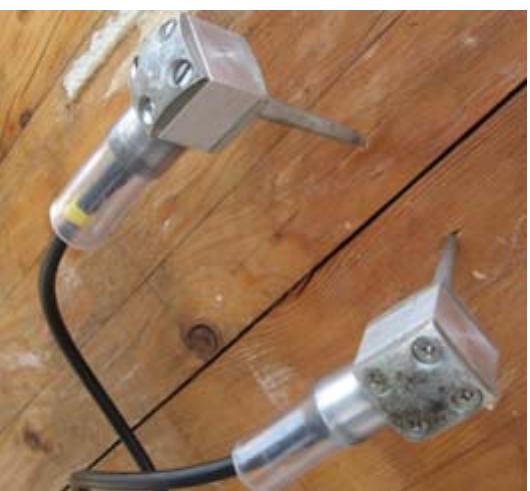
![Fig. 1. Comparison of different position of sensor on changes in magnetic response of the specimen at the same value of applied force F=550[N].](https://figures.academia-assets.com/95597851/figure_174.jpg)


![Fig. 2 Damping curves for heat treated AZ31 alloy. The damping curves for annealed alloy are shown in Fig.2. A couple of damping measurements after heat treatment was performed in same test bar as in the case of original state of Mg alloy (without heat treatment) and is marked as the 3" and 4" measurement. These results are compared ogether with damping curves for original state (® and 2" measuremen ). It can be seen that the heat treatment considerably influenced the character of damping curves, namely by occurrence of two damping maximums at the emperatures 173°C and 230°C. The damping value was 2.8x10~ for the 3” measurement, and 3.1x10* for the 4" measurement at 173 °C and approximately 4.5x10“ for both measurements at 230 °C. From Fig. 2 can be seen that maximum damping values measured for heat treated alloy are almost three times higher than that for non- heat treated alloy. That is why the maximum peaks for original state of alloy nearly disappeared. Measured damping maximums can be explained by relaxation processes took place in material for both original and heat treated state of AZ31 alloy. The relaxation processes can be connected with dislocation motion and their interaction with vacancies, impurities, secondary phases or grain boundaries [6]. For lower temperatures (to 120°C) the internal damping process is probably a result of dislocation motion in basal planes whereas at higher temperatures grain boundary sliding plays dominant role.](https://figures.academia-assets.com/95597851/figure_197.jpg)


![Fig. 2. Stress-strain relationship for abdominal aortic aneurysm cut in circumferential direction (AAAc). Obtained results indicate that incompressibility and isotropy is a reasonable assumption in that AAA tissues under uniaxial tensile tests and can be straightforward applicable to compute the constitutive modeling. They were described fairly precisely by an essential equation derived from used model ( ). The model applied is a phenomenological mode and may be called quasi-structural because of its conformity to the Holzapfel’s and Weizsacker’s postulate [8], which talks about the additive spli of the isochoric strain-energy function into parts connected with the different deformation of a structure; it’s mean connected with elastin and collagen fibres (Fig. 3). It’s very importan mathematical describe behavior of AAAs’ walls under deformation to take into consideration influence of complex structure.](https://figures.academia-assets.com/95597851/figure_202.jpg)
![Fig. 3. Collagen and elastin fibres in aortic abdominal aortic aneurysm walls. 3. References [1] G. Holzapfel, R. Ogden, Biomechanics of soft tissue in cardiovascular systems. SpringerWien NewYork (2003).](https://figures.academia-assets.com/95597851/figure_203.jpg)
![Fig. 2: Results of microhardness and RS for the tempered steel W 300 machined by graphite electrode in finishing mode. The state of residual stresses (RS) was determined by X-ray diffraction (XRD), Barkhausen noise (BN) and layer removal methods (LRM). Phase composition of cut area was evaluated by Rietveld line profile analysis from XRD data [3]. Microstructure and chemical composition of white layer and heat affected zone was investigated using optical microscope and electron microprobe with EDX analysis. The samples were also examined for microhardness HV 0.2.](https://figures.academia-assets.com/95597851/figure_204.jpg)


![Fig. 1: Requirements on reinforcing tire cords. Therefore tire steel-cords are exposed to various chemical and thermal influences (fig. 1) during cyclic loading states by _ tensile- compression in tire loading processes. The aggressive environment (e.g. action of salts in winter) activates the corroding process ym steel-cord surfaces [2]. If cords are with](https://figures.academia-assets.com/95597851/figure_218.jpg)


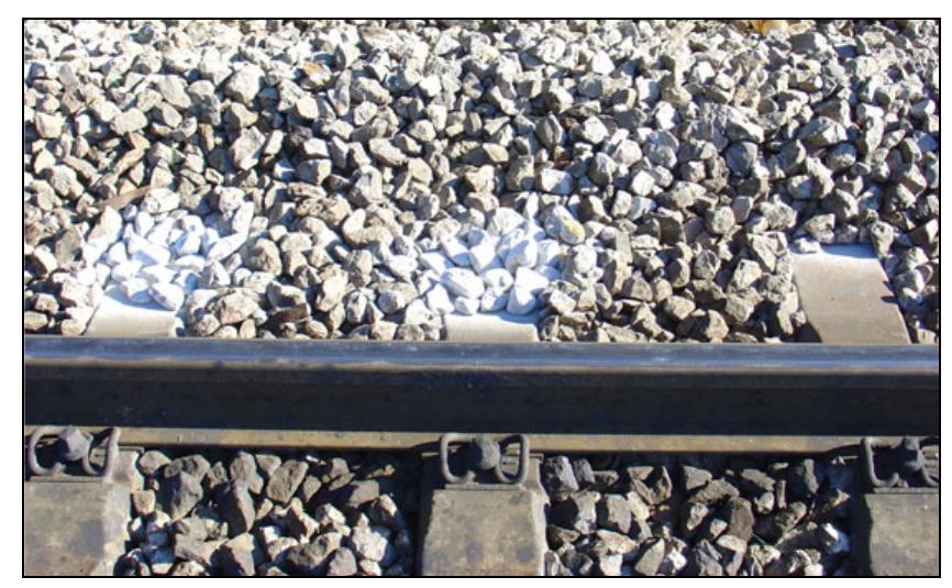
![The main elements of the upper structure of the classical rail track constructions are the rails, sleepers and the track screen (the ballast). The connection of the rails and the sleepers is achieved by an appropriate method of fastening. The Fig. 1 shows the longitudinal cross-section of the classical rail track construction, [1]. If the rail track ballast is observed, its main purpose is to elastically and equally transfer the loads caused by the rail vehicles to the plane of the lower structure, to secure the direction and height of the rail track and to dampen the vibrations in the rail track. For the ballast to fulfil the said requirements, it must have sufficient dimensions (width and thickness) and must be constructed of a good quality material. The best material for the ballast is crushed stone produced by eruptive origin. The optimal thickness of the ballast is 25 to 30 cm measured from the lower par of the sleeper (Fig. 1). This paper considers impact of the thickness of the ballast on the vertical stability of the rail rack. The measurements were performed on he rail grid of the Croatian Railways (location: Skrljevo - Meja - Pecine). The said section is in a cut and has longitudinal slope of 22 %o, hickness of the ballast amounts to 15 to 20 cm. During the year 2005 the wooden sleepers were replaced with the concrete sleepers. But, after wo years from the replacement, the new](https://figures.academia-assets.com/95597851/figure_237.jpg)


![test. Complete results for all declinations of fibres were published in [5].](https://figures.academia-assets.com/95597851/figure_248.jpg)


![Fig. 1: Experimental testing of ceramic tiles in three- point bending. The testing procedure uses the digital image correlation method and the ARAMIS system [3] as a main experimental setup. The digital image correlation method offers a precise optical solution for deformation measurements. ARAMIS is a non-contact optical deformation measuring system which analyzes, calculates and documents material deformations, being particularly suitable for three-dimensional deformation measurements under static and dynamic loading in order to analyze deformations and strains of real components. If the measuring object has only a few object characteristics, like it is the case with homogeneous surfaces, one needs to prepare such surfaces by applying a stochastic spray pattern. The experimental set-up is shown in Fig. 1, with the force applied from the top. We have to underline that some geometry imperfections were probably the cause for some](https://figures.academia-assets.com/95597851/figure_287.jpg)


![spatial motions were measured following force systems consisting of laterally directed torque T,() following triangular time functions (periodic time 21min) and static axial preloads F, with precisely adjusted force lines (+0.5mm) which served as parameter. The spatial resolution of position of the moved co-ordinate system was 0.5um for the translation of its origin and 0.5mdeg for flexion/extension. Thus, IHA-position could a. be determined as function of the flexional angle a in close approximation since small rotational angle intervals (Aa < ROM/400) were used for calculating the IHA-position, b. be related to the varying differential stiffness of the flexional angle-torque characteristics, and c. also to anatomical structures. See also: [1], [2].](https://figures.academia-assets.com/95597851/figure_294.jpg)


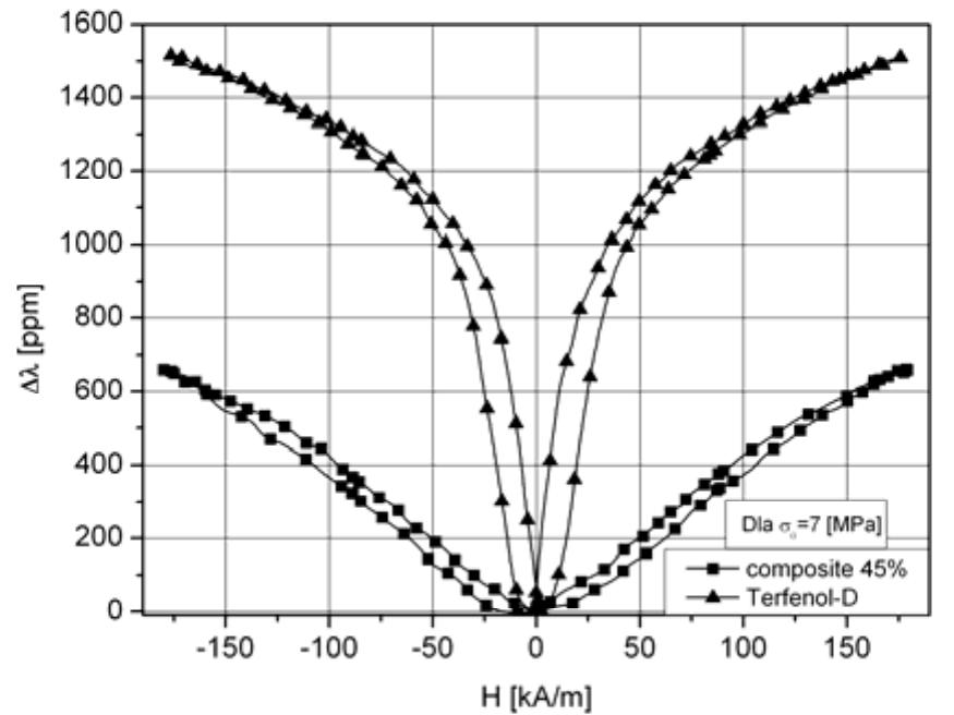
![taken into account: 1.0; 1.5; 2.0; 2.5; 3.0, and 4.0 mm, described in the work [3]. Two materials were used to fill in the tubes: foamed polyvinyl chloride (PCW) (PCHW-1-115) and foamed aluminium (ALPORAS) containing: ~97T% Al, ~1,5% Ca, ~1,5% Ti.](https://figures.academia-assets.com/95597851/figure_306.jpg)


![In the Table 1 there are compared the most important input parameters required by Biot model, obtained within the present studies with the parameters measured by the other authors, [2, 5, 7]. Analyzing the data it is worth noticing significant difference in the tortuosity used by the other authors (about 1) and in our studies 1.5+0.4, (measured min value was 1.1 maximum 2.8).](https://figures.academia-assets.com/95597851/table_018.jpg)

![Fig. 1: Sketch of experimental setup. average diameter of glass beads constituting skeleton of the material is about 260 um, while he porosity amounts 30%. Ultrasonic measurements were performed in immersion following the insertion method, [1]. The wave parameters (phase velocity and attenuation coefficient) were computed from spectrum of he broadband pulses transmitted through specimens and spectrum of the reference pulse recorded when there is no specimen between he transmitter and receiver. Experiments were done using three pairs of custom-made 10 mm- diameter unfocused ultrasonic transducers with c enter frequencies 0.5, 1, and 2 MdHz. = ransmitted signals were recorded along 2-D scans in steps of 2 mm. The radio-frequency signals were generated and acquired with 60 MHz sampling frequency, by an _ §8-bits ultrasonic programmable PC board. The scheme of the experimental setup is presented in Fig].](https://figures.academia-assets.com/95597851/figure_316.jpg)


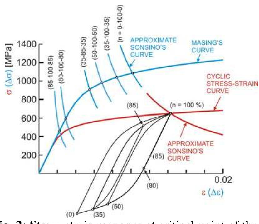
![Fig. 1: Linear stress response of critical disk part (above) with axysimmetric linear stress response of disk when it observed as blisk (down). disk When 1t obServed aS DHSK (down). According to Fig. 1 maximal equivalent SteSS Geqmax at point of expected crack initiation P (critical point) and belonging strain are unreal. It can see that critical point P corresponds to point of real crack initiation. Equivalent stress at point P’ of blisk which corresponds to critical point P of disk, taken as nominal stress o,, was served for calculation of so cold equivalent stress concentration factor Keg (Keqg=Geq(P)/On). Respecting memory of metals, real stress-strain response at critica point of disk was described by stabilized hystersis loops assigned to all simple cycles inside of engine start-stop cycles. Example of stress-strain response at critical point of the firs stage LPC rotor disk of R25-300 aero engine, for one engine start-stop cycle is shown in Fig. 2. In that figure it can see that for stress-strain response determining, cyclic stress-strain curve, Masing’s curve [2] and approximate Sonsino’s curve [1] were used. Masing’s curve was served for modelling of stabilized hysteresis loops. Equivalent stress concentration factor was used for defining of all approximate Sonsino’s curves.](https://figures.academia-assets.com/95597851/figure_332.jpg)
![The experiment has also been numerically tested using finite elements (FEM) [4] in order to estimate the optimum dimensions of the fluid container. At 2 MHz central frequency of the transducer, the ultrasonic beam has small variations of diameter, so that a depth of 50 mm and a diameter of 40mm for the container are sufficient.](https://figures.academia-assets.com/95597851/figure_334.jpg)


![Fig.5: SEM micrography of steel and coated surface To distinguish the types of damage, the surfaces of the specimen have been examined by using scanning electron microscope. The difference can clearly be seen in Fig.5. The steel surface shows a degraded and damaged wavy Structure in contrast to the coated surface, which shows nearly no damage and just a slight degradation of the coating. So the main task is to combine the results of coefficient of friction, dissipated energy, worn volume and further, the SEM analysis of the damaged surfaces to create a guideline for fretting resistance. Therefore the wear energy density ey [kJ/mm3] was calculated for both contact configurations. The result is depicted in Fig.6. It can be seen that the coated surface shows a higher value of wear energy density than the steel surface. So at first sight, it seems](https://figures.academia-assets.com/95597851/figure_350.jpg)


![Fig. 1 Shape of the load paths The results were described in [3] in detail. The new own multiaxial approaches, Papuga Critical Plane (PCr) and Papuga Integral (PD methods developed for unlimited fatigue life were investigated and published in [1], and further tested in [4]. These procedures were later enlarged also for high cycle fatigue region, as the PCF criteria.](https://figures.academia-assets.com/95597851/figure_358.jpg)


![system. Fig. 2 shows the test configuration with the analogous test model ring-on-liner. The two specimen were cut out from a real component of a gas engine from GE Jenbacher GmbH & Co OHG. An important point of all investigations is the conformity between the two specimens. To guarantee the conformity, a light-gap-methodology is applied [3]. The cylinder liner is installed in a case. This case is mounted and is linearly adjustable on he heating plate. The piston ring is installed with an adapter on the driving rod. This rod applies the reciprocating movement and the 10ormal load. On the right side of the cylinder liner the lubricant (gas engine oil) is applied via drip-feed. To ensure equivalent conditions of ‘emperature in combustion engines, the cylinder liner is heated by four heating cartridges, located beneath the case.](https://figures.academia-assets.com/95597851/figure_368.jpg)


![The outer diameter of the ring is 20 mm, inner diameter is 14 mm. Thickness of the ring is 6 mm. The diameter of the disc is 25 mm and thickness is 6 mm. There is the geometry of ring and disc test pieces with definition of necessary dimensions in the standard [5]. the time constant and equal 1500410 N. The ring is rotated through an arc of +25° at a frequency of (1 + 0.1) Hz for a given period of time (100 + 1) hours. There is distilled water using as the surrounding medium.](https://figures.academia-assets.com/95597851/figure_377.jpg)


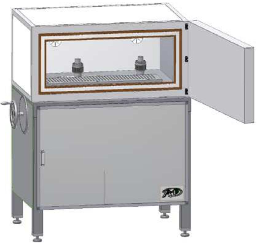
![Fig. 1: Scheme of the muddle for sample preparation To simulate the real in vivo hardening conditions to design special mould, where the required pressure for cement hardening (more then 16kPa) was provided by weights, was necessary. The scheme of the muddle is presented on Fig. 1. The samples obtained from the muddle had 4x4mm cross section and were cut into 15mm length [4].](https://figures.academia-assets.com/95597851/figure_381.jpg)


![Fig. 2: Max. stresses for 3g shock in driving direction. Numerical analysis was performed by finite element method using parabolic elements with intermediate nodes. Dynamic analysis [2] was performed by using 14 different loading models. Von Mises stresses (Fig. 2) at the region where maximum values occur are presented for simulated condition that corresponds for the 3g half-time shock directed to the driving direction.](https://figures.academia-assets.com/95597851/figure_387.jpg)


![After several months, a new problem appeared - breaking of the connecting plate of BBU support, often combined or preceeded by breaking of the screw connection (Fig. 2), even with dangerous drop away of the BBU. 2. Analysis and Experimental Results [1]](https://figures.academia-assets.com/95597851/figure_404.jpg)


![Fig.3. Kinetic fatigue fracture diagram for 40H (41Cr4 steel - heat treatment at 200°C) as a function of the energy parameter AH In the model (1), opi¢ and €g designate the cyclic yield point and critical cyclic value of deformation ¢, respectively. AH is a new criterial quantity with the [J/m*] dimension, representing the energy dissipated in each cycle of the loading spectrum. The basic advantage of that model is invariance of the diagram in relation to R ratio, and its linear character, which is illustrated at Fig. 3, by exemplary results for the 41Cr4 steel. 5. References Description of fatigue crack kinetics in the old bridge steels showing degradation symptoms (e.g. as presented in Fig 1 and 2) may prove difficult because of the material heterogeneity (large amount of impurities).](https://figures.academia-assets.com/95597851/figure_416.jpg)


![After the tests were completed, the recorded data was analyzed and force versus stroke diagrams was made [1]. Typical dependence of he compression force on the distance function obtained from investigations in the second phase of the experiment for three samples is presented in figure 3. The dependence is characterized by an approximately constant force value in the whole investigated region (for he distance of +05mm). Fig. 3: Force versus stroke diagram — phase II Figure 4 shows the dependence of the compression force versus displacement obtained by a dynamic test in the second impact energy absorption phase for a displacement of ~ 20mm. characterized by an approximately constant](https://figures.academia-assets.com/95597851/figure_420.jpg)

![Fig. 5: Prototype of absorber For European railway passenger coaches, i is recommended to have a force of absorption elements between standard buffers and car structures between 1500 and 1750 KN (per end of coach) along with a maximum stroke o 135mm [2]. Having in mind that a somewha lower force and thus energy values from the se ones were obtained in this work it was necessary to optimize some dimensions of elements. Prototype of new absorber with new dimensions was made (Figure 5).](https://figures.academia-assets.com/95597851/figure_422.jpg)


![Fig. 1: Locomotive model In order to evaluate the resistance in track curvature and wear of wheels and track, it is necessary to determine, in operating conditions, resistance force values on individual vehicle (locomotive) sections. Numerical, graphical or experimental methods can be used to solve this problem [1-2]. This work shows results of experimental analysis of the resistance force values in track curvature on individual parts of pulling vehicle — locomotive, on a scaled-down model in HO standard 1:87, with variable axle activity arrangement (WA). The experimental research was conducted with two identical four- axle locomotives (Fig. 1). 2. Measurements](https://figures.academia-assets.com/95597851/figure_424.jpg)


![Construction of the Plantograf V0O8 was designed with regards to minimisation of influence to the matrix measured points and maximisation of matrix point sensitivity. The matrix construction is described in a patent application [1].](https://figures.academia-assets.com/95597851/figure_431.jpg)


![Cast aluminum alloys are widely used in the automotive industry due to their excellent castability, corrosion resistance, and especially heir high strength-to-weight ratio. Their application for cast components subjected to dynamic loading motivates continuing study of he fatigue behavior of cast Al-Si alloys. Casting pores are the most common defects and are almost inevitable with the casting echnologies used in industry. Fatigue strength of cast aluminum heavily depends on pores formed during solidification because they favor fatigue crack initiation due to high local stress concentration, [1]. Different kinds of defects, classified as shrinkage and gas pores are shown in Fig. 1. Fig. 1: Metallographic pictures of gas and shrinkage pores in an Al-Si alloys](https://figures.academia-assets.com/95597851/figure_443.jpg)
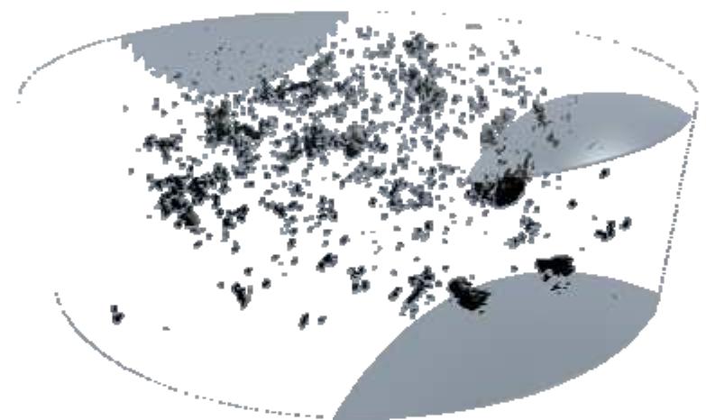
![Fig. 2: XCT images of gas and shrinkage pores geometries in 3D, [2]. Typical XCT reconstructed gas and shrinkage pores are respectively shown in figure 2.](https://figures.academia-assets.com/95597851/figure_444.jpg)


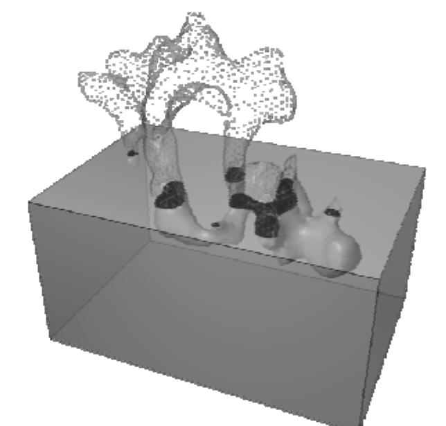
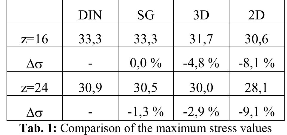
![Fig. 5: Cross-section of a gas pore than in the present 3D analysis. Results comparable to those of [3] (i.e. K=6) are obtained upon sectioning the present 3D pore and performing a 2D FE analysis (see Fig. 5).](https://figures.academia-assets.com/95597851/figure_448.jpg)

![5. References Fig. 2 Model results and measured data [2] in human (model data were A,,=2.9 cm’, L=3 cm, K=1, a =0.15, 7 =0.4, vy =0.8, 5 =10) Proposed model has been applied to the measured data in man and pig. The measured left ventricle and arterial pressure are used as input, and the calculated aortic flow is compared with measured ones in figs. 2 and 3.](https://figures.academia-assets.com/95597851/figure_450.jpg)
![Fig. 3 Model results and measured data [3] in pig (model data were A,,=1.6 cm’, L=1 cm, K=1, a=0.5, 2 =0.6, y =0.5, 5 =3)](https://figures.academia-assets.com/95597851/figure_451.jpg)


![The experimental results are shown in Tab. 1. 4. Conclusion The measured data accord with the finding of the three-point bending test executed on the same specimens [2]. Just the specimen no.5 shows the excessive values. We did not find their cause, hence we excluded it from the calculation of the mean elastic modulus. 5. Acknowledgements The research project has been supported by the research plan MSM 6840770012](https://figures.academia-assets.com/95597851/table_021.jpg)


![The plasma nitrided material 3] CrMoV9 and R935 was tested up to 10° cycles in contact low cycle fatigue. The experiments were made on three different stress levels with a test frequency of /50 Hz, with maximal nominal contact pressure 5,2 GPa, 5,9GPa_ and 6,3 GPa. Figure 2: contact low cycle fatigue line of BoR- experiments](https://figures.academia-assets.com/95597851/figure_489.jpg)

![The presented research work is connected to a running project NESC-VU, which is a European cooperative action in support of Warm Pre-Stressing (WPS) use in the Reactor Pressure Vessel (RPV) integrity assessment. WPS is a phenomenon which justifies, that crack does not propagate during unloading cycle in case of PTS. BZF takes part in the modelling work, where the WPS effects on J- integral should be determined. In the first stage of the project a preliminary calculation has been performed. An overview is given about finite element calculation of pre-cracked Charpy-like 3PB specimen, which has been performed to analyze the effect of WPS on fracture toughness value of RPV steel for two load cases (Load- Unload-Cool-Fracture and LCUF). Besides the calculation, material tests were also performed in different temperatures. Analyses on the specimen under WPS condition have been performed on a 18MND5 (A533B) ferritic steel. The material has been manufactured according to the RCC-M specifications by Creusot Loire Industrie in 1995. The material properties are provided by AREVA NP, France, [1]. True strain-stress curves from -150°C to 20°C are available for the calculation. These curves have been](https://figures.academia-assets.com/95597851/figure_491.jpg)


![Fig. 2: Definition of the critical cross section and the position of the force attack point [1] local tooth root stress is achieved. The Helix Angle Factor Ys accounts the difference of the tooth root stress between the helical gear and the equivalent spur gear which is the base of the calculation.](https://figures.academia-assets.com/95597851/figure_498.jpg)


![Fig. 1: a) Test configuration — Ring on Disc [1], b) Detail [2] Since polymeric overlays are applied in arge-area contact systems, we designed a test methodology using a large-area system. The ring on disc test configuration used here has been described in detail in previous studies [1]. A rotating disc consisting of the coated ribomaterial is rubbed against a static steel ring. The set-up, the geometry and the surface finish are depicted in Fig. 1. Splash lubrication was used using fully formulated engine oil. Temperatures (7; and 7>) and the Coefficient of Friction (COF) were measured. Several test strategies have been developed to visualize the selected system properties. Within these tests the speed was kept constant and the loading was changed in predefined steps/periods. After the test the sliding surfaces were analysed using laser confocal microscopy (Olympus LEXT).](https://figures.academia-assets.com/95597851/figure_506.jpg)


