 Mehmet Sarikaya
580 California St., Suite 400
San Francisco, CA, 94104
1996, MRS Proceedings
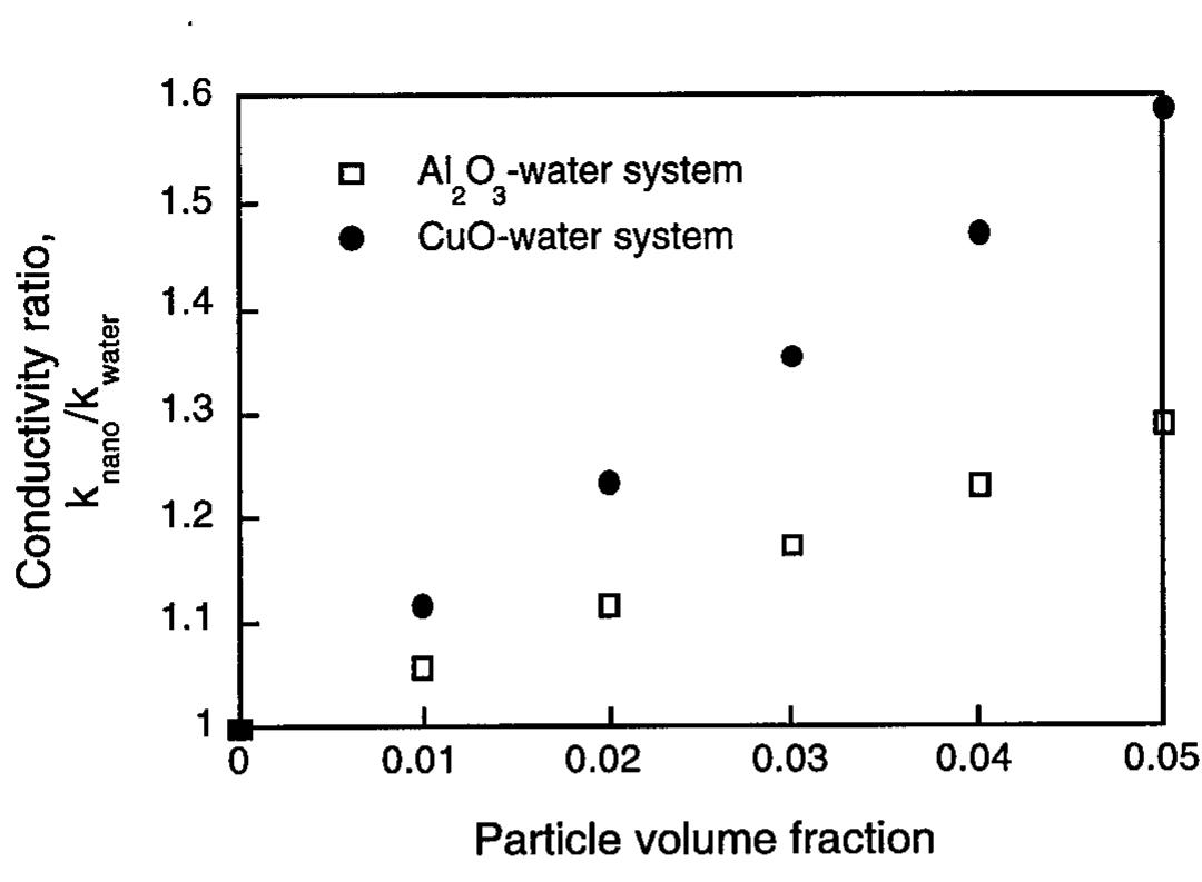
https://doi.org/10.1557/PROC-457-69This research focuses on the low temperature hydrothermal synthesis of nanophase barium titanate (BaTiO3) and barium hexaferrite (BaFe12O19) powders. It highlights the advancement in thermal conductivity achieved through the utilization of nanoparticles in fluids, offering potential applications in enhanced heat transfer systems. The study provides detailed methodologies for creating stable nanofluids and the characterization of resultant nanocrystalline powders, showcasing their implications for future thermal management technologies.


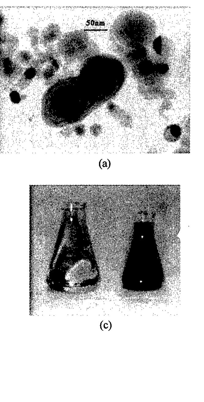
![Figure 3. Bright-field micrographs showing the typical agglomeration size of nanocrystalline (a) Cu produced by IGC and (b) CuO [5]. While the Cu in (a) exhibits a smaller grain size of approximately 18 nm compared to the typical grain size of 36 nm for CuO in (b), the CuO agglomerate sizes are smaller than those of Cu and thus CuO forms much more stable dispersions in deionized water, as seen in (c).](https://figures.academia-assets.com/47204128/figure_003.jpg)
![Figure 4. Bright field TEM micrographs of nanocrystalline Al,O3 (a) produced by IGC at Argonne (average grain size < 3 nm) and (b) purchased from Nanophase Technologies [5]. The average grain size in (b) is 33 nm. Both (a) and (b) show powders prior to dispersion in deionized water, while (c) shows the powder in (a) after dispersion. Large grains are seen after dispersion. Beakers of Al,03 dispersed in HO are seen in (d). The beaker on the right contains a stable solution of powders from (b), while the powders in the beaker on the left (corresponding to (a) and (c)) settle rapidly and are thus unsuitable for heat transfer applications.](https://figures.academia-assets.com/47204128/figure_004.jpg)

![Figure 1. Transmission electron microscopy showing the ribbon-like structure of V205,nH20 gels of the ribbons is observed when these gels are deposited onto a flat substrate. A series of 00/ peaks is observed by X-ray diffraction. The 1-D Patterson map suggests that V2Os layers are made of two V205 sheets facing each other at a distance of 2.8A [12]. The basal distance between ribbons depends on the amount of water in V20s5,nH20. It first increases by steps of about 2.8A corresponding to the intercalation of one water layer (d=8.7A for n= 0.5, d=11.5A for n=1.8 ). A continuous swelling is then observed beyond d=20A [13][14].](https://figures.academia-assets.com/47204128/figure_009.jpg)

![Figure 3. Scanning electron microscopy of cluster shell polyvanadate crystals (a) (NMeq)6[V15036C1]4H20, (b) (NMe4)10[H3V 180421] 3H20 (size of the crystals ~ 300 jum)](https://figures.academia-assets.com/47204128/figure_011.jpg)
![Figure 4. Molecular structure of cluster shell polyvanadates (a) [VisO36Cl]® , (b) [VigOgaI]!3-](https://figures.academia-assets.com/47204128/figure_012.jpg)

![Figure 1. Impedance spectra of partially sintered ceria (~ 15 nm grain size) without(w/o) contact effect and with (w/) contact resistance effect, at 550°C A: Two sides of the specimen were polished down to 1 [sm and coated with Au (0.15 um). B: One side was polished (down to 1 pm) and coated with Au. The other side was abraded with 400 grit abrasive paper. C: True sample resistance calculated from DC 4-point conductivity. Nanocrystalline ceramics are expected to have much smaller grain boundary capacitance than ~nF range, from the conventional brick layer model. The decreased capacitance can be affected by experimental artifacts, such as apparatus contributions, as reported before [4]. Also, poor contact between the specimen/electrode leads to an additional feature (i.e., an arc) as shown in Fig. 1. Poor electroding causes current-spreading at the specimen/electrode interface.](https://figures.academia-assets.com/47204128/figure_014.jpg)


![Thermopower is dictated by the charge carrier concentration irrespective of the corresponding conduction mechanism, i.e., band conduction or small polaron conduction. Bulk cerium oxide is known to conduct through small polarons between Cet3 and Cet4 [8]. The temperature dependence of thermopower (Fig. 4(a)) was used to determine the reductior enthalpy. The calculated value of 1.84 eV is much smaller than the value of 4.67~4.98 eV ir bulk cerium oxide. In combination with the temperature dependence of the electronic conductivity (Fig. 4(b)), the enthalpy of electron mobility was determined to be 0.47 eV. which is consistent with small polaron conduction. Additionally, the calculated mobility satisfied the criterion of <0.1 cm2/Vsec [9]. Based upon the chemical analysis through Spark Source Mass Spectrometry (SSMS) and the measured thermopower, the nonstoichiometry was estimated for undoped nanocrystalline ceria. It is three orders of magnitude larger than for the bulk ceria. This effect can be introduced by space charge layer formation which can mean a different activation enthalpy for defect formation (reduction). Nanocrystalline cerium oxide possesses an extremely large fraction of grain boundaries. The effect of a space charge can be amplified and thereby alter the conductivity. Although the grain boundaries are believed to have higher conductivity and higher dielectric constant, the resultant time constant is not significantly larger than the grain interiors (or the bulk). The resultant impedance spectra can be a-single arc, as shown in this work.](https://figures.academia-assets.com/47204128/figure_017.jpg)


![frustrated transition. This central peak correlates adequately with the sharp anomaly in hypersonic damping in PMN which also is caused by fluctuations [4].](https://figures.academia-assets.com/47204128/figure_024.jpg)

![Figure 1 (a)X-ray diffraction scans from nanocrystalline BaTiO, annealed at 700 °C in air for 2 hours. (b) X-ray diffraction pattern of standard polycrystalline BaTiO,. We employed a two-source evaporation process to simultaneously produce a homogenous mixture of partially oxidized Ba/Ti clusters. The processing technique and parameters have been reported somewhere else[5]. One important feature of the process used is that the Ti and BaTiO, source materials can be evaporated in an oxygen environment rather than the more common inter gas environment typically used with gas condensation.](https://figures.academia-assets.com/47204128/figure_026.jpg)


![ure 1 Schematics of zeolite and sodalite cage frameworks. Zeolites are constructed from TO, tetrahedra and each apical oxygen atom is shared with an adjacent tetrahedron [1-3]. Silicon atom forms bonds with four neighboring atoms in a](https://figures.academia-assets.com/47204128/figure_038.jpg)


![Annealing causes the relative size of the boundary arc to increase as shown in Figure 2. The coarsest sample, c-CeO,, has a still larger boundary arc (Figure 3) which is typical of polycrystalline ionic conductors in which grain boundary impedance has been attributed to impurity segregation [6, 7, 8].](https://figures.academia-assets.com/47204128/figure_046.jpg)


![Fig. 1 Images and selected area electron diffraction patterns of polyhedral nanophase TiO, (scale applies to both images). The anatase particle (a, b) is oriented along [010]. The rutile particle (c, d) is oriented along [111] and contains a twin on (011).](https://figures.academia-assets.com/47204128/figure_063.jpg)


![Contrary to pure Eu systems, the probability of depopulation through ion-ion interaction decreases as the concentration of europium ions decreases in doped systems. At sufficiently low concentration the decay mechanism is mainly radiative. This results in longer and almost exponential decay curves. In the 0.1% Eu: Y2Os nanocrystals, although the energy difference between “Dp levels for site B and C is less than the thermal energy at 10 K interaction between sites B and C appears very weak. In the cubic system also no observable interactions between Eu” ions have been reported for concentrations below 0.1% of Eu [14]. However, we notice significant energy transfer from site A to B and C in nanocrystalline monoclinic Eu*: Y203. Phonon-assisted energy transfer could be a possible explanation of this observed behavior [15]. Because of small energy mismatch between the “Dp levels of Eu at sites B and C, the one- phonon assisted energy transfer between these two sites will be inhibited as compared to transfer from site A to B and C. The fluorescence from site A appears to be inefficient as compared to site B and C. The decay characteristic of site A is rather complex and fluorescence from this site appears inefficient as compared to sites B and C. Table 1 Fluorescence decay times in monoclinic 0.1% Eu: Y20; at 10 K.](https://figures.academia-assets.com/47204128/table_005.jpg)

![After 30 hs milling time, a drop of the scattering intensity is observed over the whole q-r ympared to the 0.5 hs sample. Especially the drop at high q values is surprising since fror y measurements it is known that the average grain size is further reduced to a volume ave ‘about 16 nm which is good agreement with the average grain size derived from the RD out 15 nm after 30 hs milling. Furthermore, the RDF also shows a decrease in magni ithout any significant shift of their maxima (Fig. 3). bviously the observed change of the SANS intensity cannot be solely explained by a shi ystallite size distribution to smaller distances in real space during the milling process. Inste believed that the scattering contrast due to dislocations plays an important role for terpretation of the measured data. Since the volume dilatation in the vicinity of dislocatio nall their nuclear scattering contrast is small and disappears for pure screw dislocations | heir magnetic scattering contrast due to orientation fluctuations of the magnetic moments ¢ oms may exceed by factors up to 10-100 their contribution to nuclear scattering [15]. T uctuations are caused by magnetoelastic coupling between the magnetic moments and slocation strain field.](https://figures.academia-assets.com/47204128/figure_072.jpg)


![By simple geometric considerations [35,36] the specific grain boundary excess enthalpy is estimated to be about 2.1 J/m’. This would correspond to a value for non-equilibrium unrelaxed grain boundaries, whereas after relaxation, the grain boundary energy is reduced to 1.5 J/m’. Values resulting from computer simulations suggest excess enthalpies between 1.2 and 1.8 J/m’ it has been found that after a fast increase at early times the average grain size d changes from 16 nm to about 30 - 40 nm. The average grain size remains constant for t > 2400 sec and reaches values of 100 - 200 nm at temperatures about 600 °C. As such, two regimes with and without grain growth can be distinguished. However, since the influence of lattice point defects and lattice dislocations is negligible, the enthalpy release can be clearly assigned to the existence of grain boundaries. The reduction of the microstrains are probably caused by grain boundary relaxation and annihilation of secondary grain boundary dislocations. Based on elastic theory it is estimated that this contribution to the overall energy is less than about 5%. On this basis, the grain boundary energy can be estimated.](https://figures.academia-assets.com/47204128/figure_075.jpg)


![Fig. 5. Fracture surface observations of consolidated Ti-40 to 50%AI. (a) shows a general view of the fracture surface (b) shows the predominantly intergranular nature of the failure, with cleavage of occasional thin layers of brittle o,- Ti,Al. that a surface flaw had initiated failure. Isolated thin bands of material which had failed by formation of cleavage steps were occasionally observed, due to compositional variations within the material which resulted in formation of thin layers of brittle Ti,A]. Compression testing of stacl consolidated deposits revealed that initial plastic yielding of the material occurred at approximately 900 MPa, which is higher than for conventionally processed near gamma material [2].](https://figures.academia-assets.com/47204128/figure_081.jpg)


![The molecular silver nanocrystals under investigation here are from the same class of materials that has enjoyed rapidly growing interest in the past several years. They are charge-neutral entities comprised entirely of an elemental metal (Au, Ag, Pt) core and a dense mantle of alkylthiol(ate) surfactant groups. Elemental Ag is evaporated at temperatures ranging from 1200 to 1500 K into a flowing, preheated atmosphere of ultrahigh purity helium. The flowstream is cooled over a short distance (and flow-time) to ca. 400 K, stimulating growth of nanocrystals in the desired size- range, here ca. 4 - 6 nm. Growth is abruptly terminated by expansion through a conical funnel accompanied by dilution in a great excess of cool helium. Depending on conditions, most of the material produced is soluble in non-polar solvents, from which excess surfactant can be removed. The soluble material is found to consist entirely of nanocrystal Ag molecules (NCAM s). A Hitachi HF-2000 cold field emission gun TEM (200 kV) has been used to perform imaging and diffraction experiments. Each TEM specimen was prepared by depositing a highly concentrated drop of toluene solution of NCAMs on an ultrathin amorphous carbon film substrate, and allowing it to dry slowly in air prior to TEM observations. Nanocrystal superlattices, such as those shown in figure 1, appear on the carbon film, in the form of highly-oriented thin crystalline films, whose lateral dimensions can be as large as 1 micrometer. Our first objective has been to establish the packing structure of the nanocrystal superlattice Figure 2a shows a TEM image of an ultrathin (monolayer) film of 5.0 nm diameter NCAM: (6.4+0.2 nm center-to-center spacing), in which 2-D close-packing is deduced from the clear six fold symmetry. The electron diffraction pattern obtained from this region reveals the periodic structure of the nanocrystal lattices, and also provide an absolute calibration of the superlattice constant, because the fcc-Ag {111} ring is recorded simultaneously in the same photograph (figur 2b). Figures 2c and 2d show a TEM image and the corresponding diffraction patter corresponding to the [110] orientation, thus confirming that the superlattice has the fcc structure Such [110],-oriented films are the most frequently observed structure in our specimens, and are](https://figures.academia-assets.com/47204128/figure_086.jpg)
![very advantageous, as described previously [11], in that the projection from individual columns of nanocrystals can be viewed without obstruction by neighboring columns, allowing one to clearly view a projected shape of the nanocrystals, as we now describe. [The subscript s denotes the nanocrystal superlattice, to distinguish it from the reflections of atomic lattice of elemental Ag.] Our second objective has been to establish a relationship between this 3-D superlattice structure and the orientation of the NCAMs within it. Figures 3a andc are two TEM images recorded from the same specimen region under differing defocus conditions. Three striking features are observed. First, the superlattice contains "coherent" {200}, twin (T) and {111}, stacking fault (SF) structures. Close examination shows that the (projected) nanocrystal shape is modified across the twin boundary, accompanying the transformation in superlattice orientation. Second, profiles of the faceted structure of the NCAM cores can be seen in the image recorded at the condition close to in-focus (Figures 3a and b), and the co-aligned arrangement of these projected shapes is apparent. The majority of the nanocrystal profiles observed are consistent with the truncated octahedral (TO) morphology, which exposes {100} and {111} facets, as described previously [13]. Viewed along [110], two {100} facets and four {111} facets are projected edge-on (Figure 3b). This establishes the orientational relationship between the NCAM core's lattice and the superlattice as [110] II [110], and [002] lI [110],. Third, the image recorded at the out-focus condition exposes a web-like pattern of directional "contacts" among neighboring NCAMs, as indicated by dotted lines in Figure 3d, where the Ag cores are in dark contrast and the bright spots are channels enclosed by regions of enhanced density of surfactant chains. By comparison with Figure 3b, one can see that these dense regions interconnect between facets of Ag cores, rather than edges or vertices. It is therefore natural to suppose that the overlap of surfactant groups emanating from facets on neighboring nanocrystals serves as the prime contact which holds, or "bonds", and orients the particles in their 3-D superlattice. We further propose that materials of special type be called “highly oriented molecular (Ag) nanocrystal arrays", HOM(A)NA s. A precise orientational relationship between nanocrystal core lattices and the superlattice has Eee: PR RENN A fr Ee. Me A. er sn. Cae a a, ae” aes ee ee ae eS oe](https://figures.academia-assets.com/47204128/figure_087.jpg)
![Figure 3 [110], TEM images recorded from the a single region of a film under (a) in-focu: and (c) out-focus conditions, showing the faceted shape and the directional intermolecula bonds of the particles. The white lines indicate twin (T) planes, stacking faults (SF) and the rotation of the {111}, plane across the twin plane. An angle, a, is indicated which measure: the projected orientation between the {111} facet of a nanocrystal (dotted line) and the {111}. plane of the superlattice. A structural model for the formation of {100}, twins in the fcc superlattice is inset in (c) according to the structure model to be given in Figure 5b. (b) anc (d) are enlarged TEM images selected from (a) and (c), respectively, showing the relationshiy of the {111} and {100} facets of the truncated octahedron particles to the projected unit cel (white lines) of the superlattice. The dotted lines in (d) indicate the directional intermoleculai contacts formed by the groups of surfactant chains from facets on neighboring nanocrystals.](https://figures.academia-assets.com/47204128/figure_088.jpg)
![Figure 5. (b) A schematic model of the fec packing of the TO Ag cores and following the orientational relations of [110] Il [110], and [002] II [110],. (a) The [110], projection of the mode shown in (b). The shaded polyhedra are out-of-plane by a distance (¥2/4)a and the angle ais indicated corresponding to that shown in Figure 3a. The intermolecular interactions are represente by coils that interconnect the {111}-facets with {111}-facets on neighboring nanocrysals and {100} with {100} facets.](https://figures.academia-assets.com/47204128/figure_089.jpg)


![Fig. 1 Outline of the modified VERL process used for the preparation of metal nano- suspensions. The vacuum chamber has a diameter of 700mm.The size of the rotating stainless stee] drum is @200mm x 400mm.](https://figures.academia-assets.com/47204128/figure_095.jpg)

![Fig. 3: Mean size of Ag particles in the prepared suspensions as a function of sputtering gas pressure. The data have been derived from fits of the respective size histograms (TEM) to log-normal distribution functions. The solid line fits the data with a slope of 0.40. In contrast to thermal evaporation in the case of sputtering a second concurrent process may affect the resulting particle sizes: Keeping both sputtering current and voltage constant the sputtering rate strongly decreases with increasing gas pressure due to a reduction of the average kinetic energy of the impinging Ar atoms [3]. Here this effect shows up in a reduction of metal content of the liquid suspension with increasing gas pressure (fig. 4).](https://figures.academia-assets.com/47204128/figure_097.jpg)


![The transient reflectivity changes, AR, in the samples are shown in fig. 3 as a function of the probe delay. The time decay can be separated in three distinct time scales, each one characterized by a time constant t resulting from a fit of the curves using three exponential functions. The values of these time constants 1), t2, 13, given in Table 1, are largely different, being related to three different relaxation phenomena. Table 1 Time constants obtained from the fitting of the transient reflectivity measurements These time constants can be associated to the processes of hot-electron thermalization by electron-electron (e-e), electron-phonon (e-p) and electron-surface (e-s) collisions [4],[5]. The electron thermalization usually occurs on a subpicosecond timescale, with the formation of a Fermi distribution with T. > To (where Tp is the initial sample temperature). The hot electron system thermalizes with the lattice by e-e, but mainly by e-p and e-s collisions on a time scale of a few picoseconds [6]. The excess energy is then dispersed toward the matrix, in tens of picoseconds [7],[8], and the whole system decays to the original temperature in a time scale of hundreds of ps.](https://figures.academia-assets.com/47204128/figure_103.jpg)


![The compute-intensive part of MD simulations is the calculation of interparticle interactions. Highly efficient algorithms have been designed to compute these interactions on parallel machines [11]. The long-range Coulomb interaction is calculated with a divide-and-conquer scheme, called the fast multipole method (FMM), which reduces the computational complexity from O(N2) to O(N). For short-ranged interactions, we have employed a multiple time-step (MTS) approach in which a significant reduction in computation is achieved by exploiting different time scales for different force components.](https://figures.academia-assets.com/47204128/figure_119.jpg)
![Simulation of nanophase materials is characterized by irregular atomic distribution. Uniform spatial decomposition on parallel computers would result in unequal partition of workloads among processors and low efficiency. Recently, we have added a dynamic-load- balancing capability to an existing parallel MD code which was based on uniform mesh decomposition [13]. The new load-balancing scheme uses adaptive curvilinear coordinates to represent partition boundaries. Workloads are partitioned with a uniform 3-dimensional mesh in the curvilinear coordinate system (Fig. 2). Simulated annealing is used to determine the optimal coordinate system which minimizes load-imbalance and communication costs. Periodic boundary conditions are naturally incorporated, and the new scheme requires no change in the data structures of the MD program. The computational overhead to perform load balancing is only 3.7% of the total MD execution time for a 633,696-atom SiO, system on 32 nodes of the SP machine. Inclusion of load balancing reduces the execution time by a factor of 4.2. FIG. 2: Partition of 2,964 atoms into 2 x 2 x 1 processors: (left) curved partition boundaries in the Euclidean space; (right) uniform mesh partition in the curvilinear space.](https://figures.academia-assets.com/47204128/figure_120.jpg)

![To investigate the nature of self-affine fracture surfaces in the nanophase Si3N 4, we calculate the height-height correlation functions both in and out of the fracture plane y-z (see Fig. 4). Figure 5a shows the best fit to the out-of-plane height-height correlation function gxx(z) (= <[x(z+z,) - x(Z,)17>"”) for the fracture profile x(z) requires two roughness exponents: C, = 0.84+0.12 above a certain length scale (64A) and C, = 0.58+0.14 otherwise. The inset shows the MD results for the other out-of-plane height-height correlation function gxx(y). In this case the best fit to the results gives a roughness exponent G, = 0.7540.08. The MD results for C, and are very close to experimental values [14]. We have also determined the in-plane roughness exponent, €. Figure Sb shows that the best fit to the corresponding height-height correlation function gives C = 0.57+0.08, which is in good agreement with experiments [14]. unction gives C = 0.57+0.08, which is in good agreement with experiments [14].](https://figures.academia-assets.com/47204128/figure_122.jpg)


![size of Inm [12]. The reduction is however larger then the predicted values from the three- compound model described in reference[6]. At higher loads the curve start to deviate from linear behaviour. The inset in fig.2 shows the deviation from linear behaviour expressed in %. The exact onset of plastic deformation is difficult to determine because of the very slowly or even maybe never reached maximum deformation. In order to reduce error, values given are all strain values loading during 30 psec, when strain rate was very slow. As can be observed, the strains reached in Ni_5O are higher then those reached in Ni_15, which means that there is more plastic deformation at the lower grain size. This indicates a lowering in yield stress or a reduced hardness when grain size is reduced from 5.4 to 3.2 nm. At 5.4 nm the yield stress is between 0.1 and 0.2 Gpa, at 3.2 nm the yield stress is below 0.1 Gpa.](https://figures.academia-assets.com/47204128/figure_127.jpg)


![Fig. 2 (a) Si-N pair-distribution functions (PDF); (b) N-Si-N and (c) Si-N-Si bond-angle distributions (BAD). (Dashed and solid curves correspond to the interior regions of nanoclusters and the intercluster regions of the nanophase system, respectively.) The inset in (a) shows the first peaks in the PDF. Fig. 3. Spatial distribution of the average Si coordination, projected onto the x-y plane, in the nanophase system at 2.94 g/cc. Mw ee ee ee ee SRS We have calculated various correlation functions to determine the structure of the consolidated nanophase Si,N, at mass density 2.94 g/cc. In Fig. 2 (a), we depict partial (Si-N) pair-distribution functions (PDF) for atoms inside the nanoclusters (dashed curve) and in intercluster regions (solid curve) at 5 K. The sharp peaks in the PDF for atoms inside the clusters indicate that the interior regions of these clusters remain crystalline. On the other hand, the PDF for intercluster regions has much broader peaks (except the first one) than those inside the nanoclusters. The inset in Fig. 2(a) shows that the height of the first peak in the PDF for intercluster regions is only one fourth of the height of the first peak for interior regions. It should also be noted that the position of the first peak for intercluser regions is shifted to a lower value relative to that for the interior region of nanoclusters. This shift implies a decrease of the nearest- neighbor coordination for Si atoms in intercluster regions. Lower Si coordination in intercluster regions is also evident in Fig. 3. The figure shows that the average Si coordination in intercluster regions is approximately 3.5 which means that there are 50% three-fold coordinated Si atoms while the remaining Si atoms are four-fold coordinated. (In crystalline Si3N4 the coordination of Si is four [12].) The figure also shows that there are a few pores (black regions) inside the system. We have also examined N-Si-N and Si-N-Si bond-angle distributions (BAD) inside the nanoclusters and in intercluster regions. We find that the BADs for intercluster regions are much broader than those corresponding to the interior region of nanoclusters. This also indicates that the local structure in the intercluster regions is highly distorted [13].](https://figures.academia-assets.com/47204128/figure_138.jpg)
![Dhaest VUAUELE Iw BY LEE CUA VUE VE NA av Pee bat oY BARN WEE WEILL ANE LER PO fe CO a phase c, is calculated from the effective volume of the crystalline part of nanoclusters; and the concentration of amorphous intercluster regions c3 is determined from the condition, c+ c2+¢3= 1. The bulk and shear moduli of individual phases are obtained from MD calculations for the o- crystal and the amorphous Si;N, system [8]. (K; = G, = 0; Ky = 289 GPa and G, = 145 GPa for the o-crystal; K; = 181 GPa and G; = 109 GPa for the amorphous system.) Using those values we solved Eqs. (1) and (2) for K and G. In Fig. 5 we show these results by solid circles (K), triangles (K) and squares (G). Evidently the three-phase model for the elastic moduli explains successfully the MD results for the dependence of elastic moduli on both porosity and cluster size. The elastic moduli of amorphous $i3N4q are smaller than the crystal and a nanophase system with 45 A clusters has larger concentration of amorphous regions than the system with 60 A clusters. The system with smaller grains is therefore less stiff than the system with larger grains.](https://figures.academia-assets.com/47204128/figure_139.jpg)

![Central to the development of the nanocomposite systems examined in this study are the thermal properties of the ferromagnetic metal nitrides utilized as precursors. Their relatively limited stability allows selective decomposition at moderate temperatures, ~ 600 °C, while the ceramic matrix is unaffected. The thermal decomposition of pure CoN and FeN was examined by Suzuki et al [7,8] who conducted annealing treatments in a stepwise manner; on the other hand, the thermal decomposition of pure Ni;N was examined[6] using a continuous incremental ramp. Pure Co and Fe foils were sputtered in the present study to confirm the stoichiometry of the products formed under the experimental conditions described above. The nitrides produced in both cases were the ones with a 1:1 stoichiometry. Both elements form nitrides with lower nitrogen content, Co,N and Co;N in the case of cobalt, and in the case of iron, Fe,N asa additional phases. The thermal decomposition profile of CoN shows two nitrogen evolution events at 340 and 400°C. The integrated areas for the two events are approximately equal, suggesting a stepwise decomposition to CoN in the first step and formation of metallic cobalt in the second step. The profile is given in Fig. 1 along with the result of a run that was quenched halfway to establish weight loss and to examine the crystalline phase present at that stage. Fig. 1. Thermal decomposition profile, showing mass analyzer response to ion m/e = 28. Trace A decomposition of pure CoN quenched. Trace B pure CoN.](https://figures.academia-assets.com/47204128/figure_141.jpg)

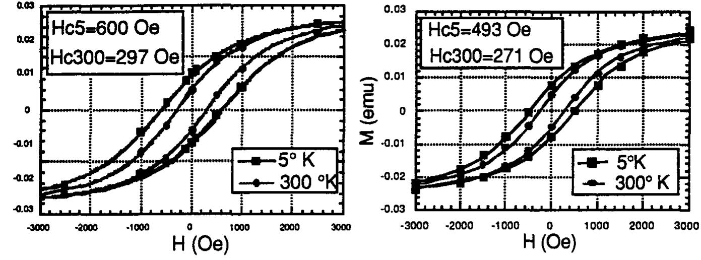
![There are extensive experimental observations of size effects on coercivity and its temperature dependence that have been explained[9] in relation to the size of single-domain particles. Coercivity reaches a maximum for single domain particles but decreases both for lar; particles that are multidomain and for smaller particles which fall within the realm of superparamagnetic behavior. Superparamagnetism is dependent on temperature and is evident above a critical temperature, the blocking temperature, Tp, above which thermal motions cont the alignment of the assembly with the applied field and the system is magnetically reversible(coercive field, Hc=0). The assembly is stable at temperatures lower than Ty and the system shows hysteresis. Experimentally we derive Ts from plots of Hc vs T’”. Ty values are 392 K for Ni/AIN, 206 K for Co/BN, 50 K for Co/SisN, and 100 K for Fe/SisN,. The coercive field at room temperature for nickel is 35 Oe; on the other hand, the other systems should not show any coercivity at room temperature under ideal conditions since the Tg values are much wPeReL Aka BD ated = Saturation magnetization of the ferromagnetic nanocomposites derived from the thermal treatment were to about 74% of that for pure metal for Ni/AIN. The corresponding figures are 94 % for Co/BN and 50 % for of Fe/Si3N,. The lower saturation magnetization is common for nanostructured metals and has been explained as arising from the oxidation of the clusters and disorder at interfaces. The iron case is somewhat more complicated since the pyrolysis has to be conducted at temperatures above 700 °C to insure that all of the nitride is converted to the metal. Under those conditions, however reaction between the metal and the ceramic matrix is possible and silicides were formed which accounts in part for the lower saturation magnetization for iron. In common with nanostructured ferromagnetic metals, the nanocomposites examined in this ctdv chawed hvcterecie unoan revereal nf the Feld in a oven temneratnre rance TTwnical](https://figures.academia-assets.com/47204128/figure_143.jpg)


![FIGURE 1: Equilibrium phase diagram of the Zn-Bi system showing the wide miscibility gap characteristic of this system [12]. In order to investigate the application of ultrasound to the formation of metal/metal matrix composites, the Zn-Bi case was selected as a model system, since both metals ar relatively easy to handle based on their chemical reactivity and low melting points. Additionally the wide miscibility gap in the Zn-Bi phase diagram (See Figure 1) made this system particularly attractive candidate for the ultrasonic formation of metallic emulsions in varyin, concentrations.](https://figures.academia-assets.com/47204128/figure_161.jpg)


![SAYERS ALY MOL do LULLY UCTIS® ao UPahiled layed Alloy layers of Al(O) can also be deposited with PLD by sequentially ablating Al and Al,( targets [6]. Composition is determined by the ratio of pulses per target, and the amount | material deposited per cycle is kept at ~1 monolayer to achieve a near-homogeneous depositio The energies of atoms in the laser-ablated plasma plume are ~10 eV, which is insufficient penetrate into the layer. However, the atoms reach the specimen with greater energies sever hundred times k,T (0.025 eV) and may thermally break surface bonds or directly displace surfa atoms, which are less strongly bound. The dark-field image in Fig. 3b shows a microstructure. 5 - 25 nm fcc Al grains with ~1 nm oxides, similar to that with ECR but on a finer scale. TI strengths of PLD alloys with 20 and 29 at.% O are 1.7 and 2.5 GPa, respectively [6], which a higher than for corresponding ECR alloys but below implanted alloys. Thus this relatively lo energy deposition method also produces a nanocomposite microstructure with high yield stress. Tes BY'D anA DT TY lasseew ol laser iret awarne eon reremanrtias wl thameaninitotad ‘allan laces](https://figures.academia-assets.com/47204128/figure_169.jpg)
![Figure 6. Nanoindentation of AlgsN5 and fit to low-load portion using indicated alloy parameters. WV REAL CUO LUPE LLU OLE WV PEWVE VLA) ae BANEE UAE CLI AD OMI 1 L1G. SU. Nanoindentation was done on a specimen implanted with 5 at.% N to a depth of 0.5 um, and the response curve is shown in Fig. 6. For loads < 0.4 mN (depths < 70 nm) the alloy layer appears quite strong; finite-element simulation using a yield stress of 2.15 GPa is seen to fit this portion of the curve well. However at higher loads, abrupt penetrations to greater depth are seen, termed “‘pop-ins” [7]. The origin of these features is not yet clear for N-implanted Al; they were not observed in O-implanted Al. Considering the initial part of the curve only, the Al,,N, alloy layer appears stronger than the corresponding Al,,O, alloy with yield stress = 1.4 GPa.](https://figures.academia-assets.com/47204128/figure_170.jpg)
![structure of AIN differs from that of cubic y-Al,O, and its bonds are more covalent. Annealed Al was implanted with 10 at.% N at room temperature and examined with TEM. Electron diffraction patterns show extra spots matching reflections of AIN, which align in the pattern of intense fcc Al reflections as in Fig. 5a. The precipitates align with the c-axis along a <]11> matrix direction and with their {1-100} planes parallel to {2-20} Al planes. Dark-field imaging with these reflections shows precipitates ~2 nm in diameter as seen in Fig. 5b.](https://figures.academia-assets.com/47204128/figure_171.jpg)


![Bilge J. ACHSNC SUCSS-SUiall CULYES OF NANOCrystaiine alloys A-f. alurntecaye et ~D.\ aluminum (69 GPa) [27]. By contrast, the stresses realized in these tests are significantly higher than the generally referenced value of the yield strength of bulk aluminum (cy=20 MPa). The stress-strain curve for nanocrystalline aluminium (A) exhibits nonlinear permanent deformation and is suggestive of dislocation motion and plasticity. By comparison, the Al-Zr alloys remained very linear and fractured with very little or no plasticity. This lack of plasticity, even at very high stresses, had been taken as a strong indication that dislocation motion is effectively inhibited or blocked in these nanocrystalline alloys. This brittle behaviour is expected when the size of the grains of a previously ductile metal is reduced to the nanometer scale [4, 23]. It is however, interesting to note that the fracture strength decreases with increasing Zr content, as seen on Fig. 5, which emphasizes the role of the flaws in this type of alloy [28]. Material from the same disks as used for samples A and B had been tested previously at Northwestern. The slightly higher values reported here, especially in the case of the more ductile sample (A) have been attributed to a miscalibration of the compliance of the glue and the strain gauge used in the previous study (but the maximum strains have been found to be very close). The fracture stresses of sample B are in decent agreement between the two studies (250 Mpa compared to 300 Mpa here).](https://figures.academia-assets.com/47204128/figure_185.jpg)


![RESULTS power diffractometer Siemens D-500 instrument at room temperature. The ND experi- ments were taken in the ISIS Rutherford Appleton Laboratory on a ”Liquids and Amor- phous Differactometer” by ”in stu” measurements of the diffraction patterns during the heat treatment. The Méssbauer spectra were measured at room temperature using a °’Co in Rh source with calibration of a-Fe foil, and fitted with a histogram magnetic hyperfine- field distribution by the Brand [7] and Hesse-Rubartsch method[8]. The sub-spectra of the nanocrystalline Fe(Si) phase were fitted by superimposing sexetets of Lorentzian li- nes corresponding to the different Fe neighbourhoods in Fe(Si) phase, in these case the Gaussian-shaped hyperfine distribution was related with the remaining amorphous phase.](https://figures.academia-assets.com/47204128/figure_193.jpg)
![Figure 2: The JMAE exponent,n, of Fe(Si) crystallization process as a function of transformed fraction, annealing the samp- les r=5 and 2=8 at 490, 500 and 510°C. beginning of crystallization is different for the different samples. This means that the controlling mechanisms during the crystallization process are different. For the sample z=5 it is an interface controlled grain growth with a increasing nucleation rate at the beginning of crystallization{9], then the nucleation rate saturates and diffusion limited growth dominates. For the sample z=8, the beginning of crystallization is diffusion con- trolled growth with increasing nucleation rate[9], and then diffusion limited growth till the end of the process.](https://figures.academia-assets.com/47204128/figure_194.jpg)


![UMBCLOSCOPYy \ 1 ioivi). BDBT was performed to characterize the mechanical behavior of both nanocrystalline anc coarse grained NiAl samples. All samples were mechanically polished prior to testing to produce « 0.0544m surface finish, A compression cage fixture was designed and built for thes measurements. A schematic representation of the BDBT apparatus is shown in Fig. 1. The 9 mn diameter specimens were freely supported on a 7 mm diameter ring and load was applied to the center of the disk through a flat punch having a 1.15 mm diameter. The BDBT load-displacemen data were analyzed following the procedures outlined in [5].](https://figures.academia-assets.com/47204128/figure_198.jpg)
![tdi") eli iia Tica aka I a a i a a with an average size of ~6 nm in this particular case. Before disk bend testing nanocrystalline NiAl specimens, the performance of the BDB’ apparatus was evaluated by testing standard coarse grained stainless steel and aluminum samples These materials have very well characterized mechanical properties. Load-displacement curve: obtained were similar to load-displacement curves obtained by other investigators on similar]; ductile materials when subjected to disk bend testing [7]. Also, yield stress and modulus value: obtained were within +5% of the literature values for the same materials tested by more conventional tensile test methods.](https://figures.academia-assets.com/47204128/figure_199.jpg)
![A representative room temperature load-displacement curve for n-NiAl-1 and coarse grained NiAl sample strained at 1.4x10⁻⁶ sec! is shown in Fig. 3. After correction for the expected initial non linear region [7], the yield stresses of nanocrystalline samples were calculated from the total loads at yielding (taking into account the sample thicknesses according to the procedures described in [5]). Yield stress values are given in Table I. Coarse-grained NiAI samples fractured prior to yielding and the stresses at fracture were typically approximately 75 MPa, well below the yield stresses of nanocrystalline samples. It has been shown by Li et al. [7] that for disk bend tests plastic yielding occurs at the onset of the deviation from linearity in the load-displacement curve and that the yield strength obtained by disk-bend testing is comparable to the tensile yield strength. A significant and most important observation in the present study is that a deviation from linearity is observed in the load- displacement curve for nanocrystalline NiAl, indicating that NiAl in nanocrystalline form exhibits yield behavior and thus measurable room temperature ductility. A deviation from linearity was not observed in eight CG-NiAl samples tested under similar conditions. Strains-to-failure of 0.1 - 0.2% and 0.016 - 0.06% were observed at room temperature in the present study for n-NiAl and CG-NiAI, respectively. The values of total strain obtained for n-NiAl samples may be hampered by the residual porosity since stress concentrations could develop at the voids resulting premature fracture. Therefore, the measured strain-to-failure values in the present case are most likely lower limits. Further improvements in ductility may be obtained if denser specimens can be obtained in the future. The failure mode of n-NiAl was determined to be ductile from postmortem examination of broken pieces using SEM, as seen in Fig. 4. The apparent improvement in the room temperature ductility in n-NiAl can be understood](https://figures.academia-assets.com/47204128/figure_200.jpg)


![Figure 5. XRD patterns of Fe-10wt.%A] powder milled for 10 min and annealed prior to (sample A) and after (sample B) the first exothermic peak and after the second exothermic peak (sample C) in DSC diagram. In order to study the kinetics of the formation of solid solution during ball milling, the ball milled Fe-4wt.%Al, which has single exothermic peak in the thermal diagram, was employed for XRD and DSC analysis. It is reasonable to assume here that the formation of solid solution consists of both a mechanically induced component (during bal! milling) and a thermally induced component (during DSC _ heating), with the latter being reflected in the DSC diagrams (As seen in Figures 3 and 4). If the thermal component of enthalpy of solid solution formation is known, the mechanical component of enthalpy of formation of solid solution may be calculated provided that the overall standard enthalpy of formation (AH{ota1) is available. In the present experiment, the standard enthalpy of formation of solid solution Fe,Al;.x (x atomic content) at 293 K can be approximated by [9]](https://figures.academia-assets.com/47204128/figure_206.jpg)


![The formation of y-TiAl in Ti/Al thin film diffusion couples has not been reported previously. It should be noted that research on compound formation in Ti/AI bilayers has been carried out for more than 20 years [13]; but there has never been any report of formation of intermetallic com- pounds other than Al3Ti in such bilayers. A possible explanation for the absence of intermetallic compounds other than Al3Ti was suggested by Gosele and Tu [14], although their model refers to planar morphologies rather than the more equiaxed transformation products observed in the present study. They introduced the concept of missing compounds in thin film diffusion couples as com- pared with bulk diffusion couples. A critical thickness is defined where a transition occurs from interfacial reaction to diffusion control of the rate of reaction. A second reaction product layer will](https://figures.academia-assets.com/47204128/figure_214.jpg)


![The final orientation studied was also an arrester type but with the crack plane perpendicular to [101] and the crack front in the [101] direction. As expected with the presence of a <110>{111} slip system two Shockley partials similar to the ones observed for pure copper and nickel, in Figure 1, were emitted. In Figure 4a, the crack was observed to close at a stress of 0.64 as the dislocations partially relieve the lattice strain. At a stress intensity of 1.28, Fig. 4b, the crack remains in its original position and two more Shockley partials were emitted. As in the pure metals, all the dislocations where of the 1/6<121> type on {111} planes. As the crack blunts, the emitted dislocations appear to stay at the interfaces. These dislocations will control the fracture behavior in this ductile orientation. Figure 2: Crack growth in the delamination orientation, (010)[001], at stresses of a). 0.32 and b). 0.48 MPa*m’”.](https://figures.academia-assets.com/47204128/figure_217.jpg)

![Figure 4: Dislocation emission in the (101)[101] orientation and stresses of a). 0.64 and b). 1.28 MPa*m’”,](https://figures.academia-assets.com/47204128/figure_219.jpg)
![ee ae a, i, Laie a a a ae these host compounds in their pure form at reduced temperatures (700- -900 °C). The principal aim of this paper is to demonstrate the feasibility of a simple polymerizable complex (PC) route, known as the Pechini method [19], for the synthesis of photocatalysts. BaTi,O, and its composites combined with RuO, have been chosen as the focus of the present work, and the PC technique was successfully applied to the synthesis of pure BaTi,O, at 700-900 °C [20]. The PC method is based on polymerization between citric acid (CA) and ethylene glyco! (EG) in the presence of soluble metal salts with required amounts to form a polyester-type resin, inside which metal-CA complex species remain soluble to sustain the scale of mixing of different metals almost molecularly homogeneous [21-27]. An important aspect of this technique in the synthesis of BaTi,O, is that the individual metal CA complexes can be immobilized in a rigid polyester network while preserving the initial stoichiometric ratio of Ba and Ti upon polymerizatior (see a schematic picture shown in Fig.1). Immobilization of the metal complexes in a rigid polymer](https://figures.academia-assets.com/47204128/figure_220.jpg)

![Fig.3 X-ray diffraction patterns of the Ba/Ti=1/4 composition powder precursor (derived from an ammonia containing solution (pH=3)) calcined in static air for 2 h at 600 °C (a), 650 °C (b), 700 °C (c), 800 °C (d), 900 °C (e), 1000 °C (f), and 1200 °C (g). One of the common problems in the synthesis of BaTi,O, by wet chemical routes is the difficulty in controlling the rapid hydrolysis of Ti-alkoxides (chemicals most frequently used as sources of Ti) compared with barium species. For instance, in the previously reported sol-gel synthesis of BaTi,O, [18], gels derived from Ba and Ti alkoxide precursors have producec strongly multiphase samples even after the heat-treatment at 1200 °C. The preferential hydrolysis of Ti-alkoxides can form Ti-rich clusters, which destroys the cation composition of the original solution. This result tells us that Ti-alkoxides should be modified by certain organic compounds such as acetic acid to control the degree of hydrolysis and subsequent polycondensation reactions [21, 28-30]. A similar event has been observed in the present PC synthesis of BaTi,O,, when the pH of the original solution was adjusted to 3 by addition of ammonia. An interesting comparisor can then be made as to phase evolution of BaTi,O, between the original Ba/Ti=1/4 CA/EG solution (pH~0.1) and the one modified by ammonia (pH~3). Figure 3 shows XRD patterns of the powder precursor (derived from the ammonia containing solution) calcined in air at different temperatures](https://figures.academia-assets.com/47204128/figure_222.jpg)


![Fig. 4. Conversely, the electrical conductivity is increased with a nanoscale SiO, addition. Asymptotic values at long times are lower than for TiO, alone, even with the classical two-phase factor [8] applied here. The chemical diffusivity measurements are shown in Fig. 3 for samples held for days at 1153°C. The plotted data for re-equilibration runs (each 1500 sec in duration) after step changes from 0.02 atm to 0.42 atm pO,. For 1153°C hold times less than 10° sec, each sample with the SiO, nanoscale addition shows markedly slower re-equilibration rates than for the baseline TiO, without SiO2. The largest initial decrements in diffusivity are found for the largest volume fraction additions. The lowest diffusivity values are partly affected by the limit imposed by the re-equilibration measurement run time and the cross-sectional area. The electrical conductivity measurements over the same days of holding at 1153°C are shown in Fig. 4. These conductivities are the based on the conductance values at the end of](https://figures.academia-assets.com/47204128/figure_257.jpg)


![The materials engineering approach afforded by nanocomposite materials has been exploited for the fabrication of complex optical filters, particularly those based on inhomogeneous designs. In such structures, reflection bands are produced as a result of interference effects in thin film ensembles with half-wave sinusoidal periodicity in refractive index. The bandwidth of the reflection peak is dependant on the refractive index excursion An around the mean value, whilst the peak reflectivity achieved depends on both An and on the total number of periods present. Multiline designs can be realised by the superimposition of individual sinusoids [13].](https://figures.academia-assets.com/47204128/figure_277.jpg)


![When combining two materials which form a solid solution, such as TiN and TiC [10], the hardness H follows the rule-of-mixture, i.e. it increases monotonously according to equation (4) (see [10]).](https://figures.academia-assets.com/47204128/figure_283.jpg)

![creased due to some yet unknown effect. In [9] we have speculated if electronic phenomena related to quantum confinement could be responsible for such effect. However, a detailed theo- retical treatment of problem is still lacking but highly desirable. Fig. 4: A typical HRTEM image of a sample with 33 mole % of SisN, showing a direct image of the (111) and (200) lattice planes of those TiN nanocrystals which have the correct orienta- tion with respect to the electron beam. The defect free nc-TiN crystallites of a fairly regular, almost spherical shape are imbedded in the amorphous a-Si3N, matrix. (See text.)](https://figures.academia-assets.com/47204128/figure_285.jpg)

![Figure 1: FE-SEM micrograph of fracture surface (a) and bright field TEM micrograph (b) of TiN specimen obtained at T=1200°C and P=4 GPa. Turning to the analysis of Table I it seems to be important to keep in mind that increase of processing temperature has resulted in hardness increase in spite of possible recrystallization effect. It can be connected not only with a small density increase but also with “strengthening” of gtain boundaries as we have pointed out [21] and also noted by Watanabe [22]. It seems very likely that a further reduction of TiB2 powder size and an optimization of high pressure sintering parameters or other high-energy consolidation methods will further increase the hardness level and the foregoing data are not the limiting values.](https://figures.academia-assets.com/47204128/figure_286.jpg)


![B72 UV Deposition of films in this study was carried out using separate targets of each carbide. This suggests that distinct carbide phases should result in the absence of any diffusion or atomic mixing processes. The deposition temperature of 400 C represents a homologous temperature of 0.2Tm for TiC, with similar values for ZrC and VC. Consideration of the diffusion of C in Ti (D ~ 10-13 cm?/s [5]) gives a diffusion distance of 144 nm after 1800 seconds. Therefore, the depo- sition temperature does not allow for significant long-range diffusion. However, the PLD process produces a significant fraction of highly energetic depositing species [6] of energies on the order of 200-400 eV. The high energies of these species can enhance atomic mixing and surface diffu- sion processes at the depositing film, which contrasts with other deposition processes where most of the depositing species are at thermal energies. eee: ame amen eA ge9 - oe . -—=—=. se ~~. ows oe»](https://figures.academia-assets.com/47204128/figure_291.jpg)


![Fig. 3 XPS spectra of Pt4f level in as-deposited Pt/TiO2 nanocomposite films with various Pt/Ti atomic ratios; (a)0.35, (b)0.21, (c) 0.18. Sea aera RE OTN NE TNC CAMELS NAY Fa NER TORTI ON AAT? CENTS UTM ANON V EN Serve eg STANTS ETE TE Sere tinte Me Mme niin! ier Figure 3 shows XPS spectra of the Pt4fsy2 : and Pt4f7/2 levels i in as-deposited Pt/Ti02 nanocomposite films. These peak positions in binding energy apparently changed among the nanocomposite films with different P/Ti atomic ratios. Table I shows XPS Pt4f7/2 binding energies for several Pt species [11]. As shown in Fig. 3, Pt4f7/2 binding energies of the nanocomposite](https://figures.academia-assets.com/47204128/figure_294.jpg)
![binding energy of TiO2 (458.7 eV) [12], indicating that the chemical state of Ti in as-deposited films was almost always TiO? with a slight reduction during the sputter deposition process in argon atmosphere. Fig. 4 XRD patterns of heated TiO (a) and Pt/TiO2 (b-e) nanocomposite films at various temperatures in air; (a), (b) 700 °C, (c) 600 °C, (d) 500 °C, (e) 400 °C.](https://figures.academia-assets.com/47204128/figure_295.jpg)
![Fig. 5 TEM photographs of heated Pt/TiO2 nanocomposite films with a Pt/Ti atomic ratio of 0.18 at (a) 500°C and (b) 600°C. temperatures. It is well known that PtO2 decomposes into Pt metal at 585 °C [13]. Thus, the Pt metal particles rapidly grow via decomposition of PtO2 at temperatures higher than 600 °C. In heated nanocomposite films with a Pt/Ti atomic ratio of 0.35 at 600 °C, the nanoparticle size ranged from 10 to 100 nm. The size of these Pt nanoparticles in the heated nanocomposite films increased with an increase in the Pt/Ti atomic ratio of the films. PTT Nkok ren rare ichen be, Se laa ceca: fee ce tain lee Snancnwa nee Pase se Sis ae i aa i a BK. i ae ie ee eS](https://figures.academia-assets.com/47204128/figure_296.jpg)


![For bulk 5CB in the nematic phase one relaxational process associated with the molecular rotation around it’s short axes was observed [9]. The characteristic frequency of this process is in MHz range. The temperature dependence of the corresponding relaxation times obeys the Arrhenius formula: t = toexp(U/kT), where U is the activation energy and k is the Boltzmann constant. In bulk nematic phase the value of U; is 0.61 eV. The dielectric behavior of 5CB dispersed in porous matrices is different from it’s bulk behavior. In confined 5CB we observe at least three identified relaxational processes. The first low frequency process (1 Hz - 10 KHz) which does not exist in the bulk is illustrated in Fig. 3 for 5CB in 10 nm pores (curves 1 and 1a) and in 100 nm pores (curves 2 and 2a). The second process is very clearly seen in the MHz frequency range and the last one, which is less visible appears in the frequency range f >30MHz. Both processes are shown in Fig. 3, curves 1b, 1c (10 nm pores) and 2b, 2c (100 nm pores). The solid lines in Fig.3 represent the results](https://figures.academia-assets.com/47204128/figure_299.jpg)
![- The relaxational process in the MHz range with 7 ~ 1078s is bulk-like and corresponds to the rotation of the molecule around the short axis. In cylindrical pores at frequencies f >1MHz the main contribution to observed dielectric relaxation is due to molecular rotation around short axis, and the process with tT ~ 1079s was less visible [7] than in random pores. The temperature ‘dependence of relaxation times corresponding to the rotation of molecules around short axis for 5CB in 10 nm random pores is presented in Fig. 4. This dependence for 5CB in pores is different from that in the bulk nematic phase. From Fig. .4 we see that ther is no indication of a sharp or well identified nematic-isotropic phase transition. Instead w observe a gradual change of relaxation times in a wide temperature range 36.5 °C< T <30.( °C. The temperature range T' < 36.5°C, where the temperature dependence of Int deviate: from linear dependence, corresponds to the anisotropic phase and Inv is not a linear functio1 of 1/T in this range. However if we consider the temperature regions T < 30.0°C anc T > 36.5°C separately then Inr = f(1/T) in these regions is reasonably well approximatec by a linear function and the corresponding activation energies are U = 0.54eV and Uj, = 0.48eV. The first activation energy U is less than the activation energy of bulk nemati phase U, = 0.6leV. This fact could be considered as an evidence for smectic type orde formation at pore wall - LC interface in this temperature range. Qualitatively for 5CB it cylindrical pores the temperature dependence of relaxation times corresponding to molecula: rotation around short axis is close to that in 10 nm pores. For 5CB in 100 nm random pore: we found that the temperature range (T < 34.5°C) corresponds to the anisotropic phase of 5CB and Inv is not a linear function of 1/T. Again if we consider the temperatur regions 34.5°C < T < 20°C and 19.5°C < T'< 9°C separately then Int = f(1/T) it each of these regions could be reasonably well approximated by a linear function and th corresponding activation energies were found to be U; = 0.74eV and U2 = 0.53eV. The firs!](https://figures.academia-assets.com/47204128/figure_300.jpg)


![Figure 4: UV-Vis absorbance spectra of different Si samples. The UV-Vis spectrum of the buik Si, milled Si powder, and nanoparticles separated by centrifugation are shown in Figure 4. The bulk Si and as-milled powder (both black in color, show an essentially featureless spectra, with absorbance increasing over the wavelength range The centrifuged nanoparticles (with dimensions of 21 and 38 nm) depict spectra unlike those observed from the under 6 nm chemically synthesized nanoparticles.[7,8,13] A sharp peal between 250 and 300 nm is observed followed by a gradual tailing of the absorbance. The peak below 250 nm appears to be an artifact based on the absorption of the solvent (ethanol) in tha! range. The absorbance from the smaller particle dimension [Si(Sh)] is blue shifted. In addition, vibronic signature is visible, especially for the Si(Sh) separated sample. We are currently investigating whether these effects are due to impurities introduced during the nanomilling process phenomenon associated with the Mie optical extinction,{1] or other extraneous effects.](https://figures.academia-assets.com/47204128/figure_304.jpg)


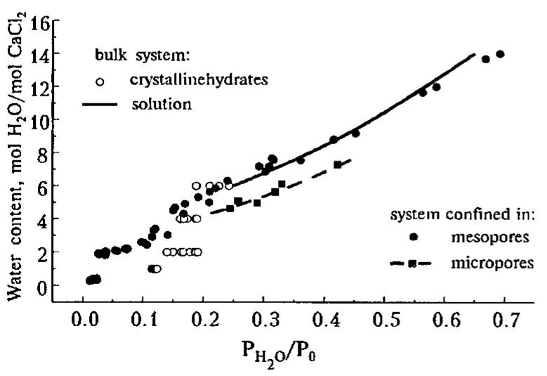

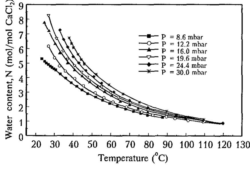
![Table I. Isosteric heat of water sorption AHj, for CaCk - H,O system confined to mesopores well as a shoulder at Nx 4. At Py0/Po > 0.15-0.2 the isotherm is a smooth curve which essentially coincides with the proper curve for the bulk aqueous solutions of calcium chloride [7]. It means that the solution confinement to mesoporous silica gel does not change its water sorption properties as compared to the bulk solution. Our DSC measurements (see below) of the specific heat of CaCl, aqueous solutions dispersed in the mesoporous matrix also have not established any changes in the C, value due to the confinement to the pores.](https://figures.academia-assets.com/47204128/figure_320.jpg)

![Fig. 1. Absorption spectra of Ag/PMMA prepared by various [Ag]o concentrations. ([BPO]p = 2.0 x 10² M, heat-treated at 120 °C for 24 h.) Figure 1 shows the absorption spectra of Ag/PMMA that were prepared by various concentrations of [Ag]o with [BPO]p = 2.0 x 10⁻² M, heat-treated at 120 °C for 24h. As expected, an absorption peak was observed around 420 nm. The absorption band grows depending on the [Ag]o and shifts slightly to shorter-wavelength side.](https://figures.academia-assets.com/47204128/figure_323.jpg)
![The formation and growth of the Ag particles were reconfirmed by TEM measurements. Figure 3 is a typical TEM photograph of the yellow colored Ag/PMMA sample, which was made by the following condition; [Ag]o = 2.8 x 10⁻² M, [BPO]p = 2.0 x 10⁻² M, and heat-treated at 120 Fig. 3. Transmission electron micrograph of a typical Ag/PMMA sample. ([Ag]o = 2.8 x 10° M, [BPO]p = 2.0 x 10² M, heat-treated at 120 °C for 24 h.)](https://figures.academia-assets.com/47204128/figure_324.jpg)
![Fig. 2. Absorption spectra of Ag/PMMA prepared by various heat-treatment durations at 120 °C. ([Ag]o = 2.8 x 10⁻² M, [BPO]p = 2.0 x 10² M)](https://figures.academia-assets.com/47204128/figure_325.jpg)
![Fig. 4. Absorption spectra of Ag/PMMA prepared by various [BPO]o concentrations. ([Ag]o = 2.8 x 10⁻² M, heat-treated at 120 °C for 24 h.)](https://figures.academia-assets.com/47204128/figure_326.jpg)
![Fig. 5. Absorption spectra of cast film of Ag/PMMA: (a) prepared from Ag/PMMA sample; (b) prepared by dissolving AgCF3CO2 in PMMA. ([Ag]o = 2.8 x 10⁻² M, [BPO]po = 2.0 x 10² M, heat-treated at 120 °C for 24 h.)](https://figures.academia-assets.com/47204128/figure_327.jpg)
![Figure 1. Detailed LFM image of a PE/PS/XE (45/55/1) sample. PE is brighter and PS darker; black spots in PE phase correspond to CB aggregates. These systems can be characterized in direct space at the nanometer scale by usin Lateral Force Microscopy (or Friction Force Microscopy) [11]. Since their friction coefficient p are different, it is possible to distinguish PE, PS, and CB particles (Figure 1). It appears fro: the collected images that PE is characterized by a higher value of p, which translates on th image to a lighter color on the gray-scale; CB appears in black, since there is almost n interaction between the tip and the CB particles; the 4: value for PS is intermediate and P therefore appears in dark gray on the image. The black spots attributed to CB particles ar observed to be dispersed only in the PE phase of a PE/PS polymer blend. This indicates that these experimental conditions (45% PE, 55% PS, and 1% XE), CB prefers to localize in the P’ phase. For this system, the percolation threshold is about 2.9%. In the case of BP-type CB, th CB particles then localize exclusively in the PS phase and the percolation threshold is abou 1n Qo4](https://figures.academia-assets.com/47204128/figure_328.jpg)


![The fracture toughness of the same samples was measured by Chevron-notched samples in a 3-point bending geometry. Interestingly, the load-deformation curve (figure 2) shows a failure qualitatively similar to that of the pure polymer, although the K;¢ decreased (Table II). At this point we should mention that there are ways to increase the fracture toughness of the nanocomposites [4] but our aim in the present study is to explore methods for mechanical characterization of the nanocomposites and identify their failure mechanisms, as it will become obvious by the TEM results. Moreover, by observing the fractured surfaces with an SEM (figure 3) it is revealed that the fractured surface of the nanocomposite is Table I The longitudinal and shear Young moduli for selected nanocomposites are shown.](https://figures.academia-assets.com/47204128/figure_340.jpg)
![In order to get more insight on the fracture behaviour, we carried out TEM observations of thin nanocomposite films under strain. This can be achieved by mounting m-thin slices of the nanocomposite —obtained either by microtoming the tensile bars or by spin casting— on a ductile copper grid with a 1xlmm mesh size [10]. Subsequently, we strain the system with a very small strain rate to a 5-10% deformation (figure 4). The ductile copper remains deformed and can keep the composite material under strain inside the TEM. In order to minimize as much as possible failure mechanisms that originate from surface properties of ultra-thin films, we used samples thicker than 0.5 wm and up to 1.5 ym, beyond which it becomes difficult to observe them with our TEM.](https://figures.academia-assets.com/47204128/figure_341.jpg)


![Summarizing, ultrasonic and 3-point bend techniques were successfully employed for the mechanical characterisation of nanocomposite materials. Furthermore, TEM studies of strained composite films revealed the failure mechanisms located mainly at the polymer- silicate interface. A way to improve the toughness of these materials is through the strength- ening of the polymer-surface binding (4, 6]](https://figures.academia-assets.com/47204128/figure_345.jpg)
![Fig. 1. Schematic structure of layered trioctahedral clays cal This paper discusses recent progress toward forming sheet silicate structures that might be used as components of electrochemical devices such as sensors and batteries. of the silicate sites are occupied there is no possibility of forming stable Alkali-O-A! positions so lithium diffusion through the lattice should be enhanced. It's formula can be represented by Li,(Mg3.xLi,)(Si4010)F2 ¢nH20. Layered silicates have been of interest recently for use as electroluminescent displays, polyelectrolytes [5-8], and organic/inorganic composites for creating stress relieving points in engineered materials [9-11]. In order to incorporate polymers within the layers it is necessary to swell the mica-like layers greater than that found for the alkali metal alone. Several types of silicates, such as montmorrilonite and fluorohectorite which have low charge densities, will expand almost continuously when placed in aqueous solutions. This generally leads to a controlled amount of polymer adsorbing onto the layers by controlling the component ratios [12]. However, there are no reports of the swelling of fluorophlogopite so a means must be found to incorporate polymers between the sheets. This paper discusses recent progress toward forming sheet.silicate structures that](https://figures.academia-assets.com/47204128/figure_346.jpg)

![Fig. 3. Lattice spacing of copper fluorophlogopite on intercalation of long chain amines. Closed circles correspond to an interleaved monolayer, whereas open circles are probably associated with a bilayer of amines, and approach the spacing observed in vermiculite [14]. Reaction of the copper fluorophlogopite with alkylamines caused a substantia expansion of the silicate lattice as shown in figure 3. The lower slope line corresponds t a single layer of amine with the nitrogen adjacent to the oxygen of the silicate and th hydrocarbon chains interleaved. The higher expansions are typical of that for a bilaye of amine, as found for vermiculite and other readily swellable clays. The slope correspond to an angle of the chains of around 60° to the silicate layer. Unlike th vermiculite where an ammonium salt is formed, in this material the amine is acting as | solvent for the cations. TGA showed that around 0.3 or 0.7 amine groups wer incorporated per (Si,Al)4019 group for the two configurations shown in the figure again consistent with single and bilayer amine configurations. Lithium Taeniolite](https://figures.academia-assets.com/47204128/figure_348.jpg)


![Fig. 4. Water hydrogens bonding the decavanadate clusters together [15]. Fig. 3. Structure of DTA,H, V;)O2g*8H,O showing the arrangement of the organic chains [15].](https://figures.academia-assets.com/47204128/figure_371.jpg)

![Fig. 6. X-ray diffraction pattern of the manganese chloride surfactant material [2] showing the layer-like nature of the compound.](https://figures.academia-assets.com/47204128/figure_373.jpg)

![The data obtained by chemical analysis (table I), IR and optical spectroscopy, XRD give the following formulas for the synthesized compounds: [LiAl(OH).]}.[Cuedta]-4H20, [LiAl(OH).]2[Coedta]-4H,O and [LiAl(OH)¢][Niedta]-4H,O. Edta is an anion of ethylenediaminetetraacetic acid forming stable complexes with transition metals. Thermal decomposition of LADH-X materials leads to dehydration and dehydroxylation of the hydroxide matrix and to the collapse red/ox process of the complex anion with the appearence of transition metal phase. DTA and mass spectral data show that the process of decomposition is a sequence of the following stages. Up to 200°C elimination of adsorbed and interlayer H2O from the hydroxide prevails. The process of dehydration of interstitially located water molecules proceeds in two stages approximately at 60-90°C (2 molecules) and 140-180°C (2 molecules) for all Medta- intercalates. Heating above 200°C results in the destruction of the hydroxide matrix. The process occurs before the decomposition of organic anion excepting LADH-[Cuedta], where both processes start near-concurrently. On a further increase in temperature, the process of thermolysis proceeds differently. For the nickel-containing intercalate at temperatures up to 300°C, the decomposition process goes with the predominent release of water molecules into the gas phase, which is caused by the destruction of hydroxide layeres. In the case of the copper and cobalt containing intercalates, water removal is accompanied by the simultaneous formation of gaseous products with 28 m/e and 44 m/e, which were referred to CO and CO, (fig.1). At temperatures above 300°C, for all compounds, one can observe not only the release of CO, CO. and H20 (18 m/e), but also the appearance of NH; and H; (16 and 2 m/e), which indicates a deep destruction of edta. The considerable content of carbon is determined in the products of vacuum decomposition, which points to the carbonization of the samples in the course of thermolysis (table I), The C/M and N/M ratios show that approximately one half of the carbon and nitrogen content is removed from the initial intercalates upon thermolysis.](https://figures.academia-assets.com/47204128/table_017.jpg)

![Fig.2. HREM microphotograph of LADH-[Niedta] decomposed in vacuum at 400°C.](https://figures.academia-assets.com/47204128/figure_376.jpg)
![Fig.3. Powder X-ray diffraction patterns of LADH-[Cuedta] before (1) and after heating (2) in air at 250°C during 20 min. Heating in air for several hours gives rise to formation of metal oxide phase and to subsequent production of spinel forms at high temperatures (above 500°C). Since the destruction of the organic anion for the ([Cuedta]-containing intercalate occurs near-concurrently with dehydroxilation of matrix, it was interesing to obtain nanophase particles in the layered hydroxide system in the case of suitable temperature and period of heating. For 20 minutes at 250°C the result was retention of the layered hydroxide and formation not of the CuO composite, but of the metal copper one (fig.3). It is attributable to the slow process of dehydroxilation of the matrix which protects the generated copper phase against Oo.](https://figures.academia-assets.com/47204128/figure_377.jpg)


