Selective laser melting (SLM) and electron beam melting (EBM) are relatively new rapid, additive manufacturing technologies which can allow for the fabrication of complex, multi-functional metal or alloy monoliths by CAD-directed,...
moreSelective laser melting (SLM) and electron beam melting (EBM) are relatively new rapid, additive manufacturing technologies which can allow for the fabrication of complex, multi-functional metal or alloy monoliths by CAD-directed, selective melting of precursor powder beds. By altering the beam parameters and scan strategies, new and unusual, even non-equilibrium microstructures can be produced; including controlled microstructural architectures which ideally extend the contemporary materials science and engineering paradigm relating structure-properties-processing-performance. In this study, comparative examples for SLM and EBM fabricated components from pre-alloyed, atomized precursor powders are presented. These include Cu, Ti-6Al-4V, alloy 625 (a Ni-base superalloy), a Co-base superalloy, and 17-4 PH stainless steel. These systems are characterized by optical metallography, scanning and transmission electron microscopy, and X-ray diffraction.


![Figure 2: A single single degree of freedom system: Comparison of the predicted chatter limit with the published data (Minis and Yanu- shevsky [1993], analog data is from Opitz [1968] and Sridhar et al. [1968]).](https://figures.academia-assets.com/41872735/figure_003.jpg)
![Milling with a 2-DOF Cutter : A two DOF milling system example is taken from Smith and Tlusty [12]. This is a half immersion-up milling of Figure 3: Analytical, multi frequency and time domain stability limit predictions for a case an- alyzed by Smith and Tlusty [1990].](https://figures.academia-assets.com/41872735/figure_004.jpg)
![Fig. 1. System boundaries of a unit process [111]. While some preliminary environmental studies for machine tools in material removal processes (e.g. turning and milling) indicate that more than 90% of the environmental impact is due to the consumption of electrical energy during the use stage [23], other authors reporting detailed analysis observe significantly larger contributions of the machine tool construction [9,42, 172,229]. With a minimum of approximately 83% and 60% of](https://figures.academia-assets.com/43077460/figure_001.jpg)
![Fig. 2. CO2PE! - UPLCI - Methodology [111].](https://figures.academia-assets.com/43077460/figure_002.jpg)
![Fig. 4. Power levels during the productive modes of an EOSINT P700 Selective Laser Sintering machine tool [110].](https://figures.academia-assets.com/43077460/figure_003.jpg)
![Fig. 3. Time distribution for SLS production modes (PA2200, layer thickness of 120 pm) [110]. The majority of discrete part casting operations occurs through sand casting (60%) [203]. The sand casting process involves pouring of molten metal into a mold composed primarily of sand and binders. The binders used are primarily chemical (thermal](https://figures.academia-assets.com/43077460/figure_004.jpg)
![Fig. 5. Time distribution for the production modes of the air bending process [52]. time share of the standby mode (mode 1) is very high as indicated in Fig. 5. On the other hand, the power levels during the standby mode are significant, ranging from 1.4 kW to 5 kW for conven- tional hydraulic press brakes with a maximum capacity between 80 and 170 ton. Similar conclusions were drawn by Shi et al. [179] for stamping processes.](https://figures.academia-assets.com/43077460/figure_005.jpg)

![Fig. 8. Distribution of the environmental impact during 1 h of EDM roughing [109].](https://figures.academia-assets.com/43077460/figure_007.jpg)
![Fig. 7. Average fixed energy breakdown adapted from [121]. As shown in Fig. 7, an average breakdown of the fixed energy ‘onsumption of machining processes is given by Li et al. [121].](https://figures.academia-assets.com/43077460/figure_008.jpg)
![Fig. 10. Specific energy demand for milling processes as function of the material removal rate (MRR) [43].](https://figures.academia-assets.com/43077460/figure_009.jpg)
![Fig. 9. Relative importance of different energy saving measures for compressed ai. systems. Adanted frnm [170] 2.4.2.1. Selective actuation of non-continuously required devices. An easy and highly effective way to reduce the electrical energy consumption can be found in selectively shutting down devices of which the functionality is not required in specific operational](https://figures.academia-assets.com/43077460/figure_010.jpg)
![Fig. 11. Power consumption in cutting mode in function of the laser output level for 7 different laser cutting machines (3 configurations combined with different CO2 laser sources with indication of the maximum achievable output level) [52]. Clarens et al. [27] provided a quantitative assessment of emissions and energy consumption as well as a semi quantitative assessment of health impacts associated with environmentally](https://figures.academia-assets.com/43077460/figure_011.jpg)

![Fig. 13. Energy cascade system [182].](https://figures.academia-assets.com/43077460/figure_013.jpg)
![Fig. 14. Influence of PPC on energy demand [163]. As pointed out above, the energy and resource consumption of process chains is rather dynamic depending on the state of the](https://figures.academia-assets.com/43077460/figure_014.jpg)
![Fig. 16. Production facility as a complex control system [82]. The complexity and sophistication in the organization of manu- facturing systems and processes necessitate a keen understanding of the organization for accurate environmental analysis. To assist in this effort, manufacturing can be broken into ‘levels of study’ across two orthogonal frameworks, spanning organizational and temporal levels.](https://figures.academia-assets.com/43077460/figure_015.jpg)
![Fig. 15. Paradigms for simulating energy flows in manufacturing systems [86,196].](https://figures.academia-assets.com/43077460/figure_016.jpg)
![Fig. 18. Schematic of strategy for increasing energy efficiency in manufacturing companies spanning process to facility level consumption and impacts [82].](https://figures.academia-assets.com/43077460/figure_017.jpg)
![Fig. 17. An integrated view of manufacturing design levels and the decisions they contain. Arrows represent the flow of information from one decision to another. Adapted from [165].](https://figures.academia-assets.com/43077460/figure_018.jpg)
![Fig. 19. Schematic of various energy control loops at the different levels of the facility [211].](https://figures.academia-assets.com/43077460/figure_019.jpg)
![Fig. 20. Industrial symbiosis at Kalundborg. Adapted from [190].](https://figures.academia-assets.com/43077460/figure_020.jpg)
![Fig. 21. The progression of industrial symbiosis relationships. Adapted from [24].](https://figures.academia-assets.com/43077460/figure_021.jpg)
![Fig. 22. Electricity generation in 2008 by type and country (top 20 countries) [204].](https://figures.academia-assets.com/43077460/figure_022.jpg)
![Fig. 23. Evolution of electricity prices in European countries [62,83].](https://figures.academia-assets.com/43077460/figure_023.jpg)
![Environmental parameters of sample batch for SLS processing [110]. Table 1](https://figures.academia-assets.com/43077460/table_001.jpg)

![Fig. 2. An example of how scouts in formation focus their sensor assets so as to ensure complete coverage. Four robot scouts sweep from left to right in a diamond formation. The wedges indicate the sensor focus for each scout. Figure courtesy of Diane Cook of the University of Texas at Arlington [7].](https://figures.academia-assets.com/75669259/figure_002.jpg)


![Fig. 4. Effect of cutting speed and depth of cut on tool life in turning Ti-5Al-2Sn (after Chandler [13]).](https://figures.academia-assets.com/50027429/figure_004.jpg)


![Fig. 8. Tool wear curves in machining Ti-6Al—4V (after Ping Chen [67,68]). 4, As a basic rule, a cutting fluid must be applied when machining titanium alloys. The correct use of coolants during machining operations greatly extends he life of the cutting tool. Chemically active cutting luids transfer heat efficiently and reduce the cutting forces between the tool and the workpiece. to the high cutting stresses and temperatures near the cutting edge, which greatly influence the wear rate and hence the tool life. Flank wear, crater wear, notch wear, chipping and catastrophic failure are the prominent failure modes when machining titanium alloys. Flank and crater wear may be attributed to dissolution-diffu- sion, attrition and plastic deformation, depending on the cutting conditions and the tool material, whilst](https://figures.academia-assets.com/50027429/figure_007.jpg)


![4uue = Average unit power requirements for turning, drilling and milling (horsepower per cubic inch/minute) (after Kahles et al. [10] Table 2 milling, tapping, broaching and planing), drilling and reaming being performed best by high-speed steel tools. Freeman [25] established the better performance of the WC/Co grades, no matter which wear mechanism is taking place. It has been found that the best grades in cutting applications are the C-2, represented by ISO K20 [37-39]. Dearnley, Grearson and Aucote [23,40], carrying out many trials involving various tool materi- als in the continuous turning of Ti-6A1—4V, also confi- rmed the K grade carbides as the best choice. They suggested that those WC/Co alloys with Co contents of 6 wt% and a medium WC grain size (about 0.8 and 1.4 um) gave the optimum performance. A recent study [41] advises that straight cobalt-base tungsten carbide cutting tools implanted with either chlorine or indium are very effective in the machining of titanium and their alloys.](https://figures.academia-assets.com/50027429/table_002.jpg)
![Typical parameters for machining Ti-6AI-4V jet engine components (after Kahles et al. [!0]) ®Axial depth. Radial depth is up to two-thirds the cutter diameter. Table 3](https://figures.academia-assets.com/50027429/table_003.jpg)


![Obviously rank [Cf(G.)] < 3. If rank [CT(6.)] = 3, then R(@)E = 0 and any motion in the plane is impossible! More generally, the limitations of the mobility of the robot are related to the rank of CY. This point will be discussed in detail hereafter.](https://figures.academia-assets.com/39671252/figure_002.jpg)


![Fig. 2. The quadratic dependency of MR fluid stress on particle saturation magnetization. Each data point corresponds to an MR fluid made from a different iron-based alloy. are seen to exhibit sub-quadratic behavior. Indeed the MR fluids exhibit an approximate power law index of 1.75 at low and intermediate fields. This subquadratic behavior is attributed to gradual particle saturation with increasing field and is, in part, predicted by contemporary models of magnetorheology [22,28]. Beyond fields of about 0.1 Tesla, the effects of bulk magnetic saturation are revealed as a departure from power law behavior. The stress response ultimately plateaus as the MR fluids approach complete magnetic saturation. Simple theory predicts that the ultimate yield stress of MR fluids is proportional to oJ? where > is the particle volume fraction and J, is the particle saturation magnetization. Fig. 2 demonstrates the quadratic dependency of MR fluid yield stress on particle saturation magnetization.](https://figures.academia-assets.com/4273121/figure_001.jpg)


![Fig. 4. The effect of average composite flux density on the elastic modulus for MR elastomers containing 10% (A), 20% (0) and 30% (x) iron by volume (adapted from Jolly et al. [29]). Experiments on double lap shear specimens of MR elastomers were reported by Jolly et al. [29]. Testing involved recording the complex modulus of various](https://figures.academia-assets.com/4273121/figure_004.jpg)


![Several commercially available MR fluids [34] Table 2](https://figures.academia-assets.com/4273121/table_001.jpg)
![Typical MR fluid properties [10] Table 1](https://figures.academia-assets.com/4273121/table_002.jpg)


![In the following section, a number of concepts and associated institutions will be related to the model presented in section 1. All of those institutions are work- ing with sustainability as the ultimate goal, and have elaborated working programs that take a systems per- spective of the kind presented in the model into account. However, their “entry points” into the model vary. This means that each has its distinct primary focus (highlighted in the respective figures, see below) from which other aspects of sustainability have been elabor- ated as secondary consequences to the primary focus. This is important to recognize in order to avoid misun- derstandings of the presentation. Differences in primary focus should lead, almost per definition, to some important differences in perspectives and experiences. When the different tools are considered, this potential synergy ought to be utilized in conscientious and deliber- ate ways, rather than being perceived solely as alterna- tives, or even “competitive” alternatives. This process has led to the development of The Natu- ral Step Framework TNSF [for references, see 10] for decision-making. It is designed for qualitative problem analysis, community building, and for the development of investment-programs in business corporations and municipalities. Its primary focus is on a comprehensive definition of level 2 in the presented model, resulting in the development of the system conditions, and on back- casting and other essential elements for strategic plan- ning in level 3 to comply with level 2 (see figure below). This intellectual approach is dependent on tools developed by others to cover the other aspects of the model. This includes more quantitative assessments of the objective of meeting the system conditions (as pro- vided by other institutions like the Factor 10 Institute, see below), and various tools to monitor the transition, for instance tools for management like ISO 14001 and for indication of progress such as LCA and the Factor concept (level 5). Furthermore, since the whole idea of TNS is to develop and disseminate a framework to guide](https://figures.academia-assets.com/46523843/figure_002.jpg)
![Ecological Footprinting (EF) [3] is a way of “bench- marking” all dematerializations under the system con- ditions (level 2 in the model). One of the major differ- ences to Factor 10 is that, with Ecological Footprinting, the outcomes of various activities in society are not determined by factors (i.e. incremental units related directly to the specific materials or material flows). The outcomes are instead measured and aggregated into units of area, i.e. as a reduction or an increase in the ecological area needed to support the activities. This is then related to an estimation of the total life sustaining area of the a a Efforts have also been done to relate the material intensity to the desired utility, MIPS (material intensity](https://figures.academia-assets.com/46523843/figure_003.jpg)

![and not just arbitrarily chosen data on emissions and energy use [37]. sustainable technology up to a viable product in the mar- ket is an essential consideration in the approach of SDT. STD focuses on some well known aspects of sus- tainability as the primary objectives of planning, and like TNSF, it also puts primary focus on the relation between the objective of planning on one hand (sustainability), and principles for the process to reaching the objectives on the other. More specifically [41]:](https://figures.academia-assets.com/46523843/figure_005.jpg)

![Natural Capitalism [9] attempts to define and describe means to connect human institutions including business within the flow of natural cycles including ecosystem services. To do so it is necessary to integrate all relevant aspects of society into an economic framework used for decision-making, particularly those aspects that are becoming increasingly scarce, or are at increasing risk. Hence, our “global commons” — the well-being of glo- bal ecosystems and the long term quality of life of all people — must be integrated into any comprehensive economic model. Such an economic model recognizes the critical relationship between the pursuit of human productivity, and thus higher income, and the greater use of natural capital. Natural capital includes not only the resources demanded by business and society, but also includes the flow of services that flow from ecosystems that are not monetized or valued. Natural Capitalism describes a set of fundamental assumptions necessary for this integration of economy, ecology and societal demands. These include viewing the economy as a sub- set of the global environment; future economic growth will be limited by natural capital rather than human- made capital; radical increases in resource productivity Because of UNEP’s central position in Society’s inter- national policy making, there are some major differences between Cleaner Production, and the other institutions presented in this survey. As demonstrated by the launch of the International Cleaner Production Declaration [44], the Cleaner Production Programme objective is to cata- lyse, in all parts of the world, Cleaner Production activi-](https://figures.academia-assets.com/46523843/figure_007.jpg)

![Fig. 1. The SCORE! — project knowledge communities relevant for system innovation [25].](https://figures.academia-assets.com/46265770/figure_001.jpg)


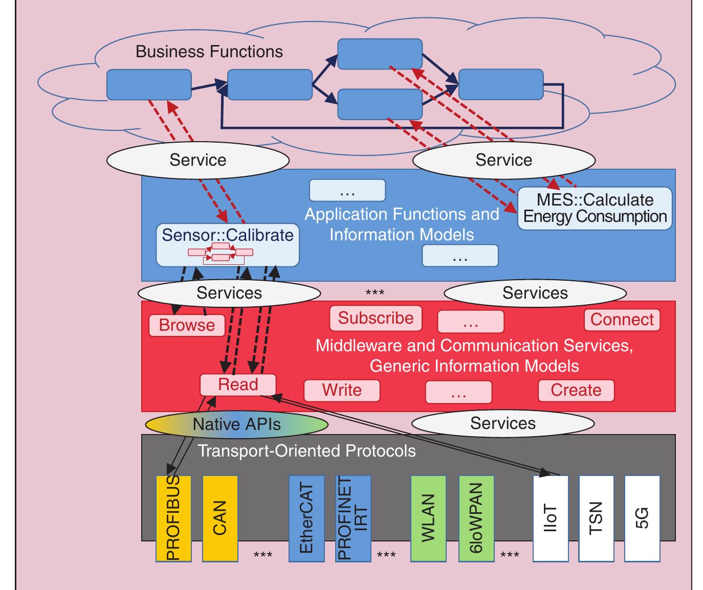
![FIGURE 2 — The complexity of communication in industrial automation systems. Today, RTE has become a standard in the industrial automation domain. Un- fortunately, there is currently no single standard but many different mutually incompatible implementations. The ex- isting RTE solutions are based on Fast Ethernet and can be divided into three classes, which differ in the achieved re- al-time performance and the necessary extensions of the IEEE 802 standards, as shown in Figure 3 [33]. In class A, the real-time services are realized above the transport layer with cycle times in the range of 100 ms. Modbus-Inter- face for Distributed Automation (IDA), Ethernet/industrial protocol (IP), and Foundation fieldbus (FF) high-speed Ethernet are implementations that be- long to this class. These were the earli- est implementations of industrial Ether- net. They build on the entire transport control protocol (TCP)/IP suite and use best-effort bridging. In class B, the real-time services are realized directly on top of the media access control (MAC) layer by using approaches like](https://figures.academia-assets.com/80786071/figure_002.jpg)


![The pros and cons of electronic information provision (adapted from Elvins [41] and Scott and Jackson [42])](https://figures.academia-assets.com/31082541/table_001.jpg)


![Classification of top 10 mining companies according to reporting formats (adapted from Satterbaxter [57])](https://figures.academia-assets.com/31082541/table_004.jpg)
![Figure 6. Covalent crosslink density of the composites stretched at vari- ous temperatures. (Solid represents unstretched; hollow represents stretched to failure). [Color figure can be viewed in the online issue, which is available at wileyonlinelibrary.com.] Above 120°C, the NR/ZDMA composites show an apparent increase in crosslink density whereas the neat NR and NR/10 phr ZDMA show a notable decrease at such high temperatures. The increase in crosslink density is an abnormal phenomenon, which is not the actual value. It is obvious that some chemical reaction occurs during stretching at such high temperatures. Note that the crosslink density of the samples preheated at](https://figures.academia-assets.com/43240793/figure_005.jpg)
![Figure 1. Effect of preheating period on the crosslink density. [Color figure can be viewed in the online issue, which is available at wileyonlinelibrary.com.] Polymer physics structure and weak chemical structure are de- pendent on the temperature. Study on the temperature depend- ence of the mechanical properties contributes to the under- standing of structure of the material. Generally, the motion of rubber chains is enhanced while the weak chemical interaction and physical adsorption between filler—filler, filler-rubber mo- lecular, and rubber molecular—molecular are severely reduced at high temperature, resulting in the dissatisfactory mechanical properties.](https://figures.academia-assets.com/43240793/figure_001.jpg)
![Figure 2. Tensile strengths at various temperatures. [Color figure can be viewed in the online issue, which is available at wileyonlinelibrary.com. ]](https://figures.academia-assets.com/43240793/figure_002.jpg)
![Figure 3. Elongations at break at various temperatures. [Color figure can be viewed in the online issue, which is available at wileyonlinelibrary. com. ]](https://figures.academia-assets.com/43240793/figure_003.jpg)

![Figure 5. Total crosslink density of the composites stretched at various temperatures. (Solid represents unstretched; hollow represents stretched to failure). [Color figure can be viewed in the online issue, which is available at wileyonlinelibrary.com. ]](https://figures.academia-assets.com/43240793/figure_006.jpg)
![Figure 8. Photograph of the NR/40 phr ZDMA composite after thermal aging for 24 h at different temperatures: (a) 80°C, (b) 100°C, (c) 120°C, and (d) 150°C. [Color figure can be viewed in the online issue, which is available at wileyonlinelibrary.com.] The strain-stress curve reflecting the whole tensile course of the rubber composite is extremely helpful for understanding the](https://figures.academia-assets.com/43240793/figure_007.jpg)
![Figure 7. Ionic crosslink density of the composites stretched at various temperatures. (Solid represents unstretched; hollow represents stretched to failure). [Color figure can be viewed in the online issue, which is available at wileyonlinelibrary.com. ]](https://figures.academia-assets.com/43240793/figure_008.jpg)
![Figure 9. Strain—stress curves of NR reinforced by ZDMA (40 phr) at var- ious temperatures. [Color figure can be viewed in the online issue, which is available at wileyonlinelibrary.com. ]](https://figures.academia-assets.com/43240793/figure_009.jpg)
![Figure 10. Strain sweep on the neat NR: (a) G; (b) G’. [Color figure can be viewed in the online’ issue, which is available at wileyonlinelibrary.com. ]](https://figures.academia-assets.com/43240793/figure_010.jpg)
![Figure 11. Strain sweep on the NR/30 phr ZDMA composite: (a) G; (b) G". [Color figure can be viewed in the online issue, which is available at wileyonlinelibrary.com. ]](https://figures.academia-assets.com/43240793/figure_011.jpg)
![Figure 12. TG (a) and DTG (b) curves for NR and NR/ZDMA (30 phr) in nitrogen atmosphere. [Color figure can be viewed in the online issue, which is available at wileyonlinelibrary.com.] To evaluate the effect of ionic crosslinks on the thermal stability, the sample of NR/30 phr ZDMA was swollen in the mixture of toluene and chloroacetic acid for 5 days to destroy ionic cross- links, then extracted by acetone for 24 h. As shown in Figure 12(a), the negligible residual weight verifies that all the ionic crosslinks have been cut off, and the Zn** have been replaced by H* which have been removed via acetone extraction. As shown in Figure 12(b), the second degradation peak is attrib- uted to the degradation of polymerized methacrylic acid (Poly- MMA) resulted from the swollen treatment. The resulting ther- mal stability shows a little decrease. The complete decomposi- tion temperature is reduced to 475°C. The two maximum rate decomposition temperatures (Tax) are 2 and 33°C lower than](https://figures.academia-assets.com/43240793/figure_012.jpg)

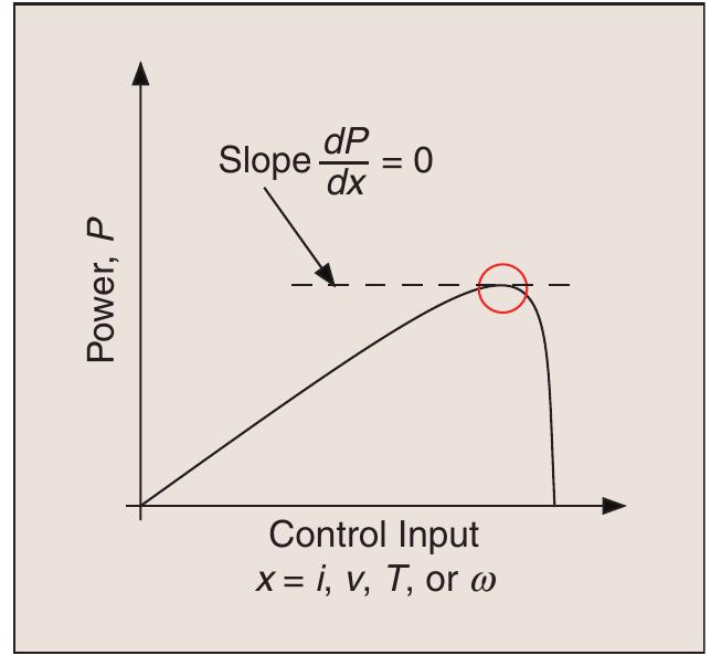
![Meeting the global demand for en- ergy is now the key challenge to sus- tained industrialization. Furthermore, modern power distri- bution systems made abundant energy reliably available and rela- tively independent from the plant location. More than two centuries of past industrialization exploited non- renewable energy resources, how- ever, often with undesirable side effects such as pollution and other damage to the natural environment. In the second half of the 20th century, extraction of energy from nuclear processes grew in popularity, reliev- ing some demands on limited fossil fuel reserves, but at the same time, raising safety and political problems. On the other hand, network and wireless communication systems have birthed another modern eco- nomic and industrial revolution. New industries and economies based on communication services have sprung up from the widespread availability of information. Harnessing information continues to change the course of technological and social development [1]. In this article, the authors suggest that the landscape or history of indus- trialization is a full circle: from energy](https://figures.academia-assets.com/40645725/figure_001.jpg)


![FIGURE 2—A possible scenario of the future power system based on smart-grid technolo- gies, with power electronic building blocks (PEBBs) and mechanical building blocks (MEBBs) as intelligent energy conversion nodes. In the next section, a possible scenario for future power systems is explored. The requirements of energy control and information flow are exam- ples of multidisciplinary cooperations A smart grid is modeled by two concentric circles—the outer circle represents energy flow and the inner circle models information flow over communication networks. Different approaches to the management of energy flow in active grids integrating distributed power generation have been proposed [11]. One of the most interesting ideas employs energy hubs to manage multiple energy car- riers (e.g., electricity, natural gas, and district heating) [12]. Within each hub](https://figures.academia-assets.com/40645725/figure_005.jpg)
![FIGURE 3—Major ICT application domains in smart grids and their correlation with grid levels. From an application perspective, there are three major domains for ICT (Figure 3). Supervisory control and data acquisition (SCADA) is already widely used for remote monitoring and controlling of higher levels of the distribution grid [17]. This area is also well covered by advanced standards such as IEC 61850 for substation auto- mation. Active distribution grids are the core of modern smart grids and enable the integration of distributed energy sources mainly into the mid- level voltage grid. The predominant task of communication in this respect is to collect critical network parame- ters and to actively influence the dis- tributed energy generation so as to maintain overall power quality. On the lower grid levels, smart metering is the most relevant use case for ICT.](https://figures.academia-assets.com/40645725/figure_006.jpg)


![Fig. 2. Portion of the category hierarchy for an environmental LCA (adapted from [21,23,24)]). MJ. Hutchins, J.W. Sutherland / Journal of Cleaner Production 16 (2008) 1688-1698](https://figures.academia-assets.com/33101060/figure_002.jpg)
![Fig. 3. Portion of category hierarchy for a social LCA. The Sustainability Reporting Guidelines were developed in conjunction with numerous stakeholders, including businesses, non-profit groups, investor organizations, and trade unions. The ef- fort was led by the United Nations Environment Programme (UNEP) and the Coalition for Environmentally Responsible Economics (CE- RES), a non-governmental organization in the United States [33]. This framework, like that of the UNDSD, organizes indicators into a four-tired hierarchy. However, the levels are termed areas (social, environmental, and economic), categories (e.g., human rights), as- pects (e.g., non-discrimination), and indicators (e.g., a description of global policy and procedures/programs preventing all forms of discrimination in operations, including monitoring systems and results of monitoring). The framework also differentiates between “core” and “additional” indicators - core indicators are those most pertinent to reporting organizations and stakeholders, other One of the fundamental questions that must be answered if we are to move forward with a life cycle assessment tool for social sustainability is: what impacts should be considered? A consensus](https://figures.academia-assets.com/33101060/figure_003.jpg)

![Fig. 5. Infant mortality vs. GDP per capita, 2003 (national data as reported in [52]). Using Eq. (2), the initial infant mortality rates predicted for the U.S. and Mexico are 4.030 and 14.30, and the total number of infant deaths would be 16,675 and 31,337. For the situation described](https://figures.academia-assets.com/33101060/figure_005.jpg)


![UNDSD theme/sub-theme framework for social dimension of sustainability [32] Table 1](https://figures.academia-assets.com/33101060/table_001.jpg)


![Fig. 1. Process flow diagram for the cement manufacturing process, showing energy and heat consumption or inputs, as well as gaseous and particulate emissions (adapted from Ref. [31]). Note that emissions at the preheating and kiln stages include both fugitive emissions and cement kiln dust or those particulates captured with controlled devices. Life cycle assessment (LCA) is a method of evaluation used to assess the environmental impacts of technologies from “cradle to](https://figures.academia-assets.com/48228092/figure_001.jpg)

![Fig. 3. Material flow diagram for the production of 1 ton of traditional Portland cement (adapted from Rundman [28]).](https://figures.academia-assets.com/48228092/figure_003.jpg)
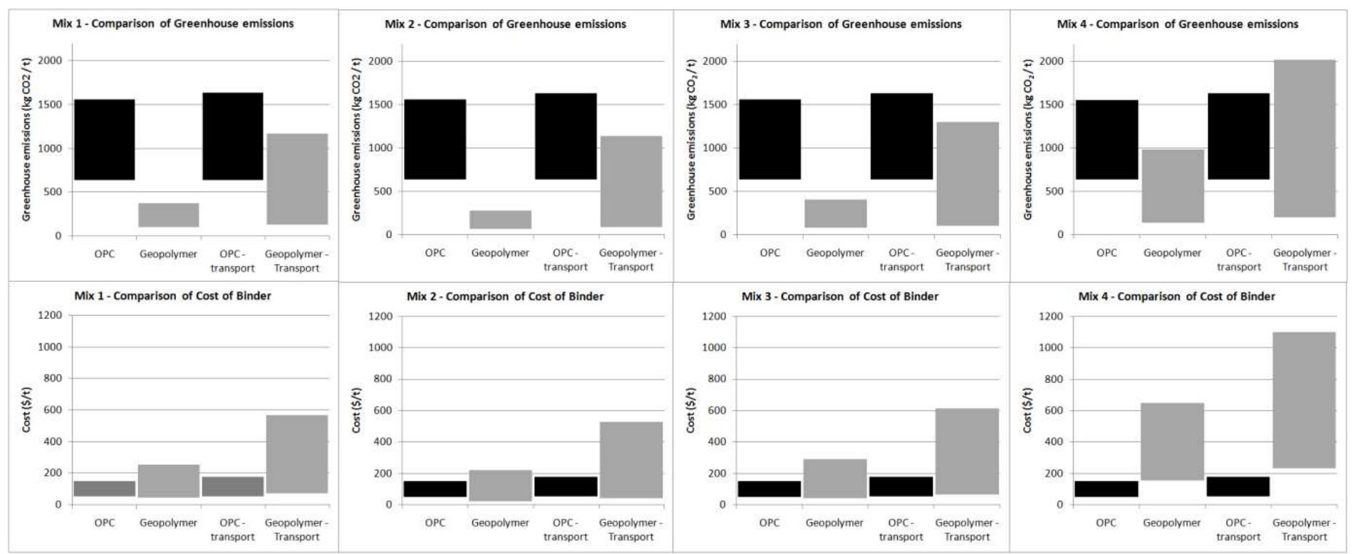
![Fig. 4. Life cycle network (cradle to gate) showing the allocation of environment impact for each step of the traditional Portland cement manufacturing process. The environmental impact score by impact categories for the four different cement products is shown below in Table 4. Of primary interest is the global warming potential of the traditional cement product versus the three (3) process/product alternatives. The main greenhouse gas generated from the manufacturing cement is carbon dioxide (COz). As mentioned previously approx- imately half of the carbon released during the manufacturing of cement originates from the calcining process (driving off CO2 from limestone to form clinker) and the remaining carbon results from the burning of fuels to fire the kiln and power the other manufacturing processes. Of the cement products examined, the blended cement has the lowest global warming potential followed by cement produced when a portion of the process related carbon emissions are captured back by sequestration in CKD. The recycling of CKD back into the kiln feed has little to no effect on reducing carbon emissions compared to traditional cement. The high impact scores for heavy metals and acidification are believed to be an artifact of the types of fuels selected and the incomplete representation of chemical interactions occurring in the kiln. For instance the actual sulfur dioxide emissions (a major contributor to acid rain) are much lower than those predicted in SimaPro. The clinker and CKD serve as partial scrubbers for SO2, removing a significant portion of the sulfur oxides (greater than 70%) in the combustion gases before they are released to the atmosphere [36]. Actual fugitive emissions of SO2 equal approxi- mately 0.27 and 0.54kg per ton of clinker produced [36,18], compared to the 4.86 kg estimated by SimaPro. As for heavy metals, the lead (Pb) content of the fuels selected (i.e. fuel oil) is assumed to be the source of the high heavy metal impact score. While heavy metals are released during the burning of many of the fuels typi- cally used during the manufacturing of cement, as with sulfur dioxide (SO), metals tend to concentrate in both the cement kiln dust (primarily) and clinker [36]. Since the focus of this assessment was global warming potential or greenhouse impact, corrections](https://figures.academia-assets.com/48228092/figure_004.jpg)
![Raw material composition of clinker, the primary component of Portland cement [7]. Table 1](https://figures.academia-assets.com/48228092/table_001.jpg)

![Energy consumption by fuel type in 2000 by the United States cement industry (from Ref. [18]). kMt: thousand metric tons and ML: million liters.](https://figures.academia-assets.com/48228092/table_003.jpg)

![Figure 1: Micromachining capability over time [2]. and where it fits relative to other microfabrication processes. Alting, et al [5] covers a broad range of fabrication techniques for small scale parts and placed microfabrication processes relative the broader field of “microengineering” and discussed the design of microproducts. This paper focuses primarily on material removal by geometrically defined cutting edges for the purpose of creation of precise three dimensional workpieces with dimensions in the range of a few tens of nanometers to some few millimeters. The motivation for increasingly smaller components parallels the improvements in cutting technology as outlined in [2]. Demand for reduced weight, reduced dimensions, higher surface quality and part accuracy, while at the same time decreasing component costs and reducing batch sizes for components of devices ranging from electro-mechanical instruments to medical devices force us along Taniguchi’s curve. These are the forces driving miniaturization. The response of the scientific community has been energetic but mixed. That is, while the development of machine tools for micromachining follows more traditional paths of scaling down conventional](https://figures.academia-assets.com/42590404/figure_001.jpg)
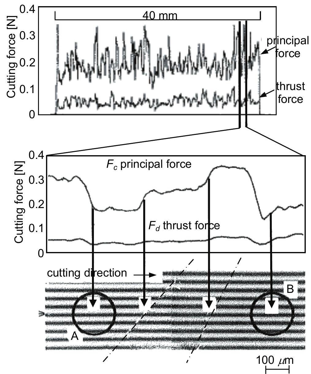
![Weule et al. [16] concluded that the roundness of a cutting edge is very important in micromilling due to the size effect. Since the tool edge is relatively large compared to other tool dimensions and the tool is relatively weak due to micro- tool fabrication methods, it is important to choose proper cutting parameters.](https://figures.academia-assets.com/42590404/figure_002.jpg)


![Figure 6. Lucca et al. [32] also found that the total specific energy is seen to significantly increase at small depths of cut in micromachining of OFHC copper. Hence, the specific energy is closely related to the minimum chip thickness and can be another indicator for cutting mechanism changes and process control.](https://figures.academia-assets.com/42590404/figure_006.jpg)

![Figure 8: Micromachined chips of aluminum showing folded sections in the form of a curl [44].](https://figures.academia-assets.com/42590404/figure_009.jpg)
![The aforementioned FE modeling is primarily for isotropic micromachining where no crystallographic effects were considered. Chuzhoy et al. [63, 64] developed a FE model for micromachining of heterogeneous material, Figure 11. Their model was capable of describing the microstructure of multi phase materials and thus captured the microcutting mechanism in cast iron. Microcutting of multi phase materials exerts larger variations in the resulting chip shape and the cutting force than seen in cutting of a single phase material. Figure 11: Computed equivalent stress for 125 wm depth of cut and 25 yam edge radius at t=0.00012 s with (a) ferritic workpiece, (b) ductile iron workpiece [63].](https://figures.academia-assets.com/42590404/figure_011.jpg)
![Figure 12: Actual (left column) and simulated (right column) microstructures of different ferrous materials [65].](https://figures.academia-assets.com/42590404/figure_012.jpg)


![Figure 16: Components of cutting force per unit width in round edge cutting model (friction coefficient: 0.3, rake angle: 0°, workpiece: copper (CDA110), edge radius of the tool: 0.01 sm) [90].](https://figures.academia-assets.com/42590404/figure_016.jpg)
![Figure 19: Various microgrooves and their fabrication by rotational cutting tools [111]. One of the more interesting applications of micromachining is in micropattern generation either on flat or curved surfaces. These patterns can work as reflectors, abrasives, and other functions. Traffic signs, Fresnel lenses, and possible CMP (chemical mechanical planarization) pad surfaces are typical examples. Various microgrooves can be created by feeding a rotating cutting tool along one direction relative to the workpiece, as illustrated in Figure 19 [111].](https://figures.academia-assets.com/42590404/figure_017.jpg)
![Figure 20: Various kinds of trapezoid microgrooves (first row: 20 wm, second row: 50 wm depth) [unpublished data from Y. Takeuchij]. Changing the angle and depth of groove, six different trapezoid microgrooves were created on a brass surface, as shown in Figure 20. The grooving was done with cutting conditions of 50 mm/min feed rate, 13 m/sec cutting speed, and 1 wm depth of cut for finishing and 5 wm for rough cutting. A diamond tool was used to create the trapezoidal microgrooves. With respect to these grooves, it was found that the machined surfaces are very smooth with sharp edges similar to more _ conventional V-shaped microgrooves. Trapezoidal microgrooves were successfully applied to bond two small parts without adhesives.](https://figures.academia-assets.com/42590404/figure_018.jpg)
![Figure 18: Process chain of micro-injection molding [110]. Bissacco et al. [110] investigated a wide range of processing methods for mold fabrication. Figure 18 illustrates the process chain for micro-injection molding for micro-fluidic systems. MEMS technology provides high precision processing capabilities but is very limited in achievable shapes allowing only molds in 2.5-D and those with a number of stackable layers.](https://figures.academia-assets.com/42590404/figure_019.jpg)
![Figure 17: Portion of micromilled trenches with stepped and straight walls (scale bar = 100 wm) [106]. Freidrich and Vasile [106] were able to produce trench features 8 «am wide and 62 um deep for an aspect ratio of nearly 8, over a length of 8 mm, Figure 17. This aspect ratio is good enough for most micromolding applications including X-ray masks.](https://figures.academia-assets.com/42590404/figure_020.jpg)


![Figure 22: Machined 3-focus micro-Fresnel lens [113].](https://figures.academia-assets.com/42590404/figure_024.jpg)

![Figure 27: Coordinate relationship in tool making and machining [3].](https://figures.academia-assets.com/42590404/figure_026.jpg)
![Figure 26: Principle of elliptical vibration cutting [103]. Egashira) and Masuzawa [123] conducted _ similar microdrilling tests using ultrasonic vibration but the vibration was applied to the workpiece instead of the tool. Quartz glass work material and a sintered diamond tool were used for the tests and they succeeded in drilling holes as small as 5 wm diameter.](https://figures.academia-assets.com/42590404/figure_027.jpg)
![Figure 28: Commercial 5-axis control ultraprecision machining center [132]. Furukawa et al. [130] built a machine using alumina-based ceramics for the structural members because of their high rigidity and thermal reliability and surface-restricted type aerostatic slideways to avoid friction. Takeuchi et al. [131] developed a 5-axis ultraprecision milling machine using non-friction servomechanisms for the creation of 3D microparts with translational resolution of 1 nm, rotational resolution of 0.00001 degree, and slideway straightness of about 10 nm/200mm. Figure 28 shows a commercial 5-axis ultraprecision machining center employing aerostatic guideways and coreless linear motors to provide non- contact, high resolution drive mechanisms achieving 1nm motion accuracy. To ensure thermal stability, alumina ceramics were used for structural components [132].](https://figures.academia-assets.com/42590404/figure_028.jpg)
![Figure 29: Scaling effect on tool geometry and wear (work material: 40CrMnMo/7, 50 HRC, cutting speed: V, = 200/100 m/min, depth / width of cut: a, = ae = 0.04 xd, feed: f, = 0.01 x d, number of teeth: 2, down milling, tool material: cemented carbide with TiAIN coating) [47]. Fabrication of micro-tools is another challenge in micromachining. Imprecise geometry and the irregularity of tools often negate the advantages of ultra precision process control, state of the art machine tools, and ultra fine tuning of process parameters. Figure 29 a-c shows the tool geometry deviation with respect to the size of the tool; as the tool size decreases from 2 mm to 0.2 mm, the deviation of the given tool geometry from the tool design increases. Also, scaling effects can play a significant role in process physics, which are closely related to the cutting mechanism, caused by a change in tool geometry during cutting. Figure 29 d-f demonstrate tool wear occurring during the micromilling of hardened steel as a function of the engagement length and tool diameter [47].](https://figures.academia-assets.com/42590404/figure_029.jpg)
![Figure 30: Overviews of produced micro-tools under optimum machining conditions: (a) Ultra precise tool (b) Extremely large aspect ratio micro-tool [155].](https://figures.academia-assets.com/42590404/figure_030.jpg)
![Figure 32: Micro-end milling under dry ice supply (work material: NiTi shape memory alloy, cutting speed: V, = 19 m/min, depth of cut: a, = 10 um, width of cut: a, = 10 ym, feed: f, = 20 um, micro-end mill: cemented carbide with TiAIN coating, d=400 um, nozzle distance: 80 mm, intermittent supply of dry ice) [47].](https://figures.academia-assets.com/42590404/figure_032.jpg)


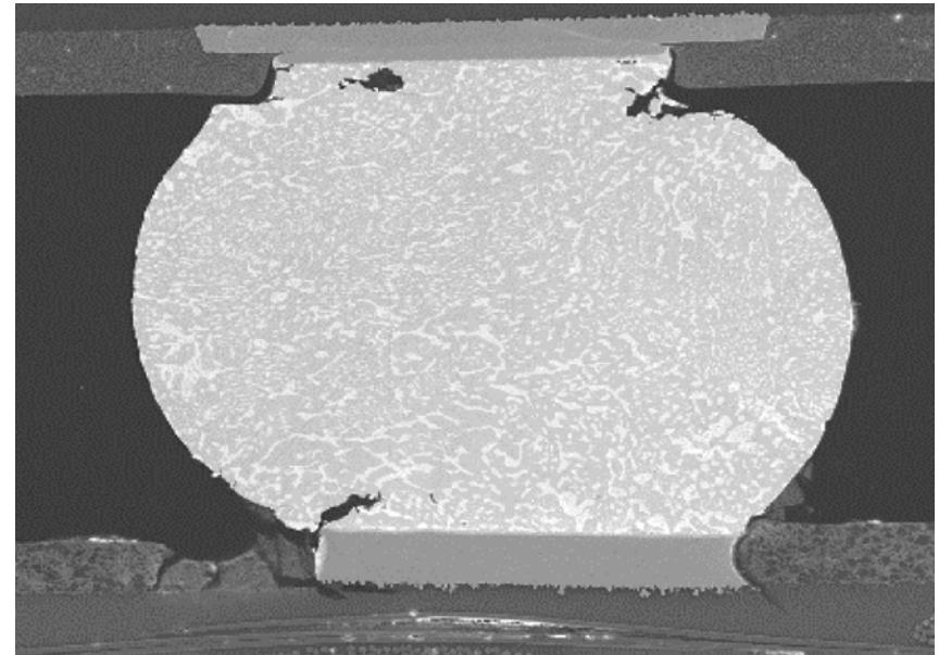
![Solder ball elements were meshed in ANSYS with VISCO107 elements, whereas all other package materials were meshed with SOLID45 elements. Fig. 4 shows the three-dimensional (3-D) quarter symmetry finite-element models for C2LBGA. ANSYS was used to simulate the thermal cycle fatigue. The quarter symmetry model was used with in this study. This constitutive law has been used by Darveaux 3]-[7] in development of damage relationships. The constitu- tive behavior model has therefore been kept the same to enable benchmark of damage relationships. Anand’s model is split into a flow equation and three evolution equations that describe the strain hardening or softening of the materials (Table II).](https://figures.academia-assets.com/44072665/figure_003.jpg)


![Fig. 8 Geometry and position of the neutral axis of PCGE-A> conventional piezoceramic processing methods corresponding to high energy density piezoelectric composition 0.9Pb(Zr0.56 Ti0.44)03-0.1Pb[(Zn0.8/3 Ni0.2/3)Nb2/3]03 +2 mol% MnO2 (PZTZNN) and 0.8[Pb(Zr0.52Ti0.48)03]-0.2[Pb(Zn1/3 Nb2/3)03] (PZTPZN). They concluded that power harvesting largely depended upon piezoelectric strain constant and the piezoelectric voltage constant.](https://figures.academia-assets.com/65865036/figure_008.jpg)


