sean faris
580 California St., Suite 400
San Francisco, CA, 94104
AI
The paper explores the potential of utilizing ocean thermal energy in conjunction with solar and wind systems to create hybrid energy solutions. It discusses the underlying principles of photovoltaic cells, including the role of p/n junctions in generating electric fields, and examines the necessary components for a functional energy system. Additionally, it presents models and case studies focused on developing countries with suitable ocean thermal resources, highlighting geographic and temperature conditions that facilitate energy generation from ocean sources.


![FIGURE 1.1. p—njunction of the PV cell. The two semiconductors behave like a battery, creating an electric field at the surface where they meet, called the p/n junction. This is a result of the flow of electrons and holes. The electrical field forces the electrons to move from the semiconductor toward the negative surface to carry current. At the same time, the holes move in the opposite direction, toward the positive surface, where they wait for incoming electrons [8]. gia 7 Rae eer](https://figures.academia-assets.com/33302759/figure_005.jpg)

![A solar energy system consists of several components, as shown in Figure 1.3. Several PV modules are connected in series or in parallel, depending on the voltage and energy requirements of the PV array. The direction of the PV arrays toward the sun might be controlled by the position motors allowing the motion of the panels horizontally and/or vertically. The sun tracking system takes the data from sun sensors or photodiodes and processes the data to determine the motor positions for the best illumination position of the PV array directed to the sun. This position detection and adjustment is similar to a mechanical power point tracking technique [18]. On the other hand, due to the voltage- current and current-power characteristics of the PV array, the electrical maximum power point (MPP) may vary based on operating current and voltage. Therefore, an electrical maximum power point tracking (MPPT) system is needed to operate the PV array at the MPP. This can be done through a DC/DC converter. Tyo Le LL ee oe et Li le 8 ee LL OL Ld ee ew ee ee nee bn L] Lee che ne TOUT ow mee ee se ee eeae](https://figures.academia-assets.com/33302759/figure_007.jpg)


![The I-V characteristic of the solar cell can be alternatively defined by [21]](https://figures.academia-assets.com/33302759/figure_013.jpg)


![it they rollow the opposite trend, the current reference should be reversed. The initial value of the current can be zero or any closer value to the Iypp, that is, the current at the MPP. On the other hand, choosing an appropriate incremental step (Alter) can quickly approach the operating point to MPP. This process should be repeated until the maximum available power from the PV array is found and extracted. The oscillation can be minimized with smaller perturbation steps. However, small step sizes cause the slow response of the MPP tracker [33]. The solution to this problem can be found using variable perturbation steps as addressed in [32,34-36]. In this method, the perturbation size should become smaller while approaching the MPP.](https://figures.academia-assets.com/33302759/figure_025.jpg)


![Fuzzy Rule Base Table TABLE 1.3 and goes to zero while becoming closer to the MPP. Generally, the output of the fuzzy logic controller is the change in duty ratio AD of the power converter. This change in the duty ratio can be looked up in a look-up table such as Table 1.3 [50], right after E and AE are calculated and converted to the linguistic variables.](https://figures.academia-assets.com/33302759/table_002.jpg)


![1.5.8 Ripple Correlation Control-Based MPPT There are voltage and current ripples on the PV array due to the switching events of the connected power electronic converter. Therefore, the power output of the PV array may also contain ripples. These ripples are used in ripple correlation control (RCC) [66] to perform MPPT. RCC correlates the time derivative of the time-varying PV array power p with the time derivative of the time-varying PV array current i or voltage @ to drive the power gradient to zero, in order to track the MPP. The operating point is below the MPP (V < Vypp or! < Iypp) if v or iis increasing (0 > 0](https://figures.academia-assets.com/33302759/figure_033.jpg)

![FIGURE 1.32 DC link capacitor droop control. The computation of PV array power is not required in this method. However, when compared to the methods that detect the power directly, this method has lower accuracy [72], since the response of the DC-voltage control loop of the inverter directly affects its response. where V is the voltage across the input voltage of the power converter and Vjink is the voltage across the DC link. If Viink is fixed, the extracted power of the PV array can be controlled by varying the input current of the inverter. The voltage Vjink can be kept constant as long as the power required by the inverter does not exceed the maximum available power from the PV array while the current is increasing; otherwise Vjink droops. The current control command of the inverter (Ipeak) is at its maximum value and the PV array operates at the MPP right before that point. To achieve the MPP, d is optimized to bring Ipeak to its maximum value in order to prevent Viink from drooping. This droop can be prevented by feeding the AC system line current back. Se ny ee a ly a rr i er : Os ie ee:](https://figures.academia-assets.com/33302759/figure_035.jpg)


![FIGURE 1.37 (See color insert following page 80.) Pyypp, FE, and y variations versus the shading factor S. where Eo is the illumination of unshaded cell and As is the shaded area. Figure 1.37 gives the MPP, fill factor, and efficiency under various shading factor values. The efficiency and fill factor suddenly drop for shading factors larger than a certain point. The power performance of the shaded PV cell almost linearly decreases as the shading factor increases [75].](https://figures.academia-assets.com/33302759/figure_041.jpg)


![FIGURE 1.42 Isolated DC/DC converters: (a) H-bridge DC/DC converter, (b) series resonant H-bridge DC/DC converter, and (c) push-pull DC/DC converter [77].](https://figures.academia-assets.com/33302759/figure_046.jpg)


![FIGURE 1.46 Fly-back current-fed inverter. The fly-back current-fed inverter shown in Figure 1.46 can be controlled to provide a rectified sine-wave output current into the inverter and to track the MPP [82]. The current into the fly-back converter is discontinuous and hence a buffer capacitor should be used to eliminate both low- and high-frequency ripples.](https://figures.academia-assets.com/33302759/figure_050.jpg)


![FIGURE 1.58 Single-stage inverter for multiple modules. A typical single-stage inverter for multiple modules is depicted in Figure 1.58, which is the simplest grid connection topology [85]. The inverter is a standard voltage source PWM inverter, connected to the utility through an LCL filter. The input voltage, gen- erated by the PV modules, should be higher than the peak voltage of the utility. The](https://figures.academia-assets.com/33302759/figure_062.jpg)
![FIGURE 1.59 A multilevel converter topology. ORR na Reinie en gaye eoeme wee Mtn pe Sein irene En, Me ae Rea ee Reem ee, eet SNe eee ee pecie RS ot eh three-level inverter can be expanded into five, seven, or even more levels by adding more modules and switches [87,88]. This allows for further reduction of the harmonic distor- tion. Drawbacks of this topology are the high number of required semiconductors and imbalanced loading of the different PV strings. Therefore, maximum power transfer from each individual string can be difficult to reach, especially when moderate shading occurs. To obtain a positive voltage at the inverter’s output terminals, upper switches S; and S» should turn on, while to obtain a negative voltage the lower switches 53 and S4 should conduct. In order to obtain zero voltage, the two intermediate switches should be turned on, that is, Sz and $3. The DC bus voltage should be greater than grid voltage amplitude in order to transfer power to the grid. Thus, a higher number of PV modules or individual boost DC/DC converters can be employed to achieve the desired voltage levels. In this](https://figures.academia-assets.com/33302759/figure_063.jpg)
![system, each of the PV strings is connected to the neutral point of the grid through the capacitors. This results in reducing the capacitive ground currents. In addition, the negative effect of these currents on electromagnetic compatibility is decreased [89,90]. However, a disadvantage of this topology is to load the DC source only during a half cycle, which increases the size of the decoupling capacitors and increases the cost of the inverter. The output voltage is 0, +Vac, or —Vac for a or 2a degrees, as shown in Figure 1.61 [91]. By controlling the a interval, the output voltage of the inverter can be controlled. TM laes: eedene eeopicen cil Ble mnnbencdkermn easier: wean hoa eaweeemoen «eo](https://figures.academia-assets.com/33302759/figure_064.jpg)

![FIGURE 1.62 Output inductor current for an HBDC inverter ee ee In configuration Figure 1.64b, the strings can operate at their individual MPP; therefore a better overall efficiency is expected. APV system composed of strings with an individual DC/DC converter, a common grid-connected inverter, and the generation control circuit (GCC) is shown in Figure 1.65, which consists of two buck—boost converters with a common inductor [92]. The left leg of the inverter can control the voltage across each string individu- ally. The upper switch along with the freewheeling diode in the lower switch and the input](https://figures.academia-assets.com/33302759/figure_066.jpg)


![Another topology for multimodule multistring interfaces is shown in Figures 1.71 and 1.72 [80,93]. The inverter in Figure 1.71 consists of three boost converters, one for each PV string, and a common half bridge PWM inverter. The circuit can also be constructed with an isolated current- or voltage-fed push-pull or full-bridge converter [93], similar to the circuit in Figure 1.72, and a full-bridge inverter in order to connect to the utility. The voltage across each string can be controlled individually [80,93].](https://figures.academia-assets.com/33302759/figure_074.jpg)


![FIGURE 1.100 Distributed solar panel and power tracker configuration. The electrical power system of a solar EV is shown in Figure 1.101, which consists of two different DC voltage buses for the traction and auxiliary power requirements [106]. This topology also contains an external outlet to charge the batteries in the case of a plug-in hybrid EV. Ultracapacitors can also be used to capture the braking energy at higher efficiencies and may help overcome the transient conditions of the vehicle, such as acceleration or hill climbing, due to their faster response times. Utilizing ultracapacitors will also reduce the](https://figures.academia-assets.com/33302759/figure_099.jpg)


![FIGURE 1.110 (See color insert following page 80 for [a].) (a) Solar-powered aircraft and (b) aircraft power train. (Modified from Y. Perriard, P. Ragot, and M. Markovic, IEEE International Conference on Electric Machines and Drives, pp. 1459-1465, May 2005.)](https://figures.academia-assets.com/33302759/figure_110.jpg)


![Wind speed is one of the most important parameters in determining the available wind power. Therefore, it is important to accurately monitor and measure it. Wind speed distri- bution can be measured by a cup anemometer. The cup anemometer works on the principle of simple measurement of the number of revolutions per minute. Data acquisition systems are used to store data for a long period, for instance one year [3].](https://figures.academia-assets.com/33302759/figure_114.jpg)


![Wind Power Classes Si a I aaa Another important factor for wind turbine siting is roughness of terrain. There are rough- ness classes, which explain the relation between wind speeds and landscape conditions. Roughness class varies from 0 to 4, where class 0 represents water surfaces and open terrains with smooth surfaces, and class 4 represents very large cities with tall build- ings and skyscrapers. Two key parameters regarding the different geographical locations affect the wind turbine siting: the friction coefficient and the roughness classification [5]. The friction coefficients are based on different terrain characteristics and are shown in Tahle 72.2.](https://figures.academia-assets.com/33302759/table_004.jpg)


![FIGURE 2.9 Speed versus power with respect to different pitch angle values. where w is the rotor speed, R is the length of the blades, and v denotes the wind speed. In addition, the power coefficient depends on the pitch angle, whichis defined as the angle between the blade surface and the plane of the wind rotor, as shown in Figure 2.9. There is a great difference between an onshore and offshore wind turbine’s power coefficient. For onshore turbines, for example, the blades are designed such that the optimal tip speed is limited to roughly 50-70 m/s, because the blade tips cause excessive acoustical noise and can cause damage at higher speeds. On the other hand, the noise does not play an important role in offshore turbines and higher speeds lead to slightly higher optimal values of Cp [10].](https://figures.academia-assets.com/33302759/figure_123.jpg)

![FIGURE 2.11 Connection scheme of a typical small wind turbine. c NS ( ( ( ( ( c ( ' [ ( ( ' c 1 ( { g a Large wind turbines are of MW power range. These turbines incorporate complex systems, and wind farms typically consist of several to hundreds of those large turbines. One of the world’s biggest wind turbines is located in Emden, Germany [13], built by the German company Enercon as an offshore turbine. The price of 1 kW installed power from a large wind turbine is significantly less than the price of 1kW from a small turbine. Currently, the installed price of a large turbine is about $500/kW, and the price of energy is around 30-40 cents/kWh, depending on the site and turbine size. Enercon turbines have a power output of 5MW with a rotor blade diameter of 126m, sweeping an area of over 12,000 m2 [13].](https://figures.academia-assets.com/33302759/figure_125.jpg)


![Since the real-time waveform of the induced EMF in the BLDC generator is not a sinu- soidal waveform, it contains harmonics. The trapezoidal waveform is generated by the machine design. All the harmonics have to be included, and in the single-phase BLDC generator, the average power can be expressed as [17-20]](https://figures.academia-assets.com/33302759/figure_130.jpg)


![FIGURE 2.24 PMSG with a rectifier /inverter. NETS RETA SS SSAC SS Bi SL Figure 2.25 shows a PMSG where the PWM rectifier is placed between the generator and the DC link, and PWM inverter is connected to the utility. In this case, the back-to- back converter can be used as the interface between the grid and the stator windings of the PMSG [35]. The turbine can be operated at its maximum efficiency and the vari- able speed operation of the PMSG can be controlled by using a power converter that is able to handle the maximum power flow. The stator terminal voltage can be controlled in](https://figures.academia-assets.com/33302759/figure_140.jpg)

![several ways [36]. In this system, utilizing the field orientation control (FOC) allows the generator to operate near its optimal working point in order to minimize the losses in the generator and power electronic circuit. However, the performance depends on the knowl- edge of the generator parameter that varies with temperature and frequency. The main drawbacks are the cost of the PMs that increases the price of the machine, and the demag- netization of the PMs. In addition, it is not possible to control the power factor of the machine [14] @ ee ee ee a 4 =e Bete: ig = ee c4< em Specie](https://figures.academia-assets.com/33302759/figure_142.jpg)


![for synchronous machines in similar applications. If the induction machine is connected to the grid, the required reactive power can be provided by the power system [40]. The induction machine may be used in cogeneration with other synchronous generators or the excitation can be supplied from capacitor banks (only for stand-alone self-excited generators application) [41-46]. The self-excitation phenomenon in an induction machine can be easilv explained using](https://figures.academia-assets.com/33302759/figure_145.jpg)


![FIGURE 2.34 Conventional control scheme for the induction generator. 1s used to meet the power demand at the desired power factor. The main purpose of an impedance controller is to keep the total real and reactive powers at a constant level. In the case of any load changes, the impedance controller will absorb the active or reactive power, which has not been used by the load. The excess power will be redirected to Rg, and will be consumed on this resistance. Thus, the total reactance of the system is adjusted as a function of the duty cycle of the chopper switch as shown in Figure 2.35. On the other hand, the excess power, which is not absorbed by the load, will be released through the resistor. Therefore, the prime mover requires no regulation and can always be operated at the required power, voltage, and frequency [56]. The imnedance controller can reoulate the voltage and frequency of the induction cen-](https://figures.academia-assets.com/33302759/figure_151.jpg)


![FIGURE 2.38 Induction machine controlled by a back-to-back inverter. Wound rotor induction machines can be supplied from both the rotor and stator sides. The speed and the torque of the wound rotor induction machine can be controlled by Figure 2.39 presents a topology that consists of a DFIG with AC/DC and DC/AC convert- ers, as a four-quadrant AC/AC converter using isolated gate bipolar transistors (IGBTs) connected to the rotor windings. In the DFIG topology, the induction generator is not a squirrel cage machine and the rotor windings are not short circuited. Instead, the rotor windings are used as the secondary terminals of the generator to provide the capability of controlling the machine power, torque, speed, and reactive power. To control the active and reactive power flow of the DFIG topology, the rotor side converter (RSC) and GSC should be controlled separately [59-62]. TTATW..... J] ... 4... *.. J... 214°... 2... 2 210 *.. 2. 2 2 2 LL 2 1°] J CO. 2 dL et de ltl | kw el let nw tl Yt Od)](https://figures.academia-assets.com/33302759/figure_154.jpg)
![FIGURE 2.40 (a) DFIG steady state and (b) dynamic equivalent electrical circuits. In the rotor circuit, two voltage-fed PWM converters are connected back-to-back, while the stator windings are directly connected to the AC grid side, as shown in Figure 2.40. The direction and magnitude of the power between the rotor windings and the stator windings can be controlled by adjusting the switching of the PWM signals of the inverters [68-70].](https://figures.academia-assets.com/33302759/figure_155.jpg)
![regulating voltages from both the rotor and the stator sides of the machine. The DFIG can be considered as a synchronous/asynchronous hybrid machine. In the DFIG, like the synchronous generator, the real power depends on the rotor voltage magnitude and angle. In addition, like the induction machine, the slip is also a function of the real power [63]. DFIG topology offers several advantages in comparison to systems using direct-in-line converters [64,65]. These benefits are as follows:](https://figures.academia-assets.com/33302759/figure_156.jpg)


![FIGURE 2.45 Voltage and frequency control using energy storage. Having additional energy storage decreases the system inertia, improves the behavior of the system in the case of disturbances, compensates transients, and therefore improves the overall system efficiency [78]. However, it adds to the initial cost of the system and requires periodical maintenance depending on the storage devices.](https://figures.academia-assets.com/33302759/figure_161.jpg)

![FIGURE 2.47 Energy storage with bidirectional converter in DFIG systems. The produced excess energy of a wind generator can also be converted to kinetic energy and stored in this form by using a flywheel. In this approach, the flywheel can be driven by another induction generator and this induction generator can be controlled by a cascaded bidirectional rectifier/inverter topology [89]. This energy can be converted to electrical energy for future use if the power production of the wind generator is not sufficient. The flywheel energy storage systems can be used as power regulators over short periods of time for electrical power quality improvement and to alleviate the volt- age and frequency fluctuations. Therefore, the storage system’s lifetime and efficiency can be increased [90-93]. These systems improve the power quality of the energy produced by wind generators and, therefore, they can be connected to the grid with less fluctuations and harmonics [94].](https://figures.academia-assets.com/33302759/figure_163.jpg)


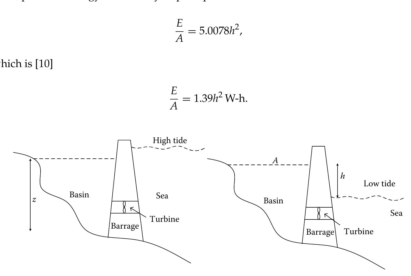
![FIGURE 3.7 Gravitational effect of the sun and the moon on tidal range. molecule to the moon/ sun. Due to the less distance between the moon and the earth, the moon exerts 2.17 times greater force on the tides as compared to the sun [8]. As a result, the tide closely follows the moon during its rotation around the earth, bulging along the axis pointing directly at the moon. When the sun and the moon are in line, whether pulling on the same side or on the opposite side, their gravitational forces are combined together and this results in a high “spring tide” [6]. When the moon and the sun are located at 90° angle to each other, their gravitational force pulls the water in different directions, causing the bulges to eliminate each other’s effect. This results in a smaller difference between high and low tides, which is known asa “neap tide” [6]. The concepts of spring tide and neap tide are shown in Figure 3.7. The period between the two spring tides or neap tides is around 14 days, half of the lunar cvcle. The range of a spring tide is commonly about twice as that of a neap tide, whereas](https://figures.academia-assets.com/33302759/figure_184.jpg)

![reaches coasts or continental shelves, bringing huge masses of water into narrow bays and river estuaries along a coastline. At some sites, the tidal flow can be heightened to more than 10m by the complex resonance effects. Bay of Fundy, in Canada, where the greatest tides in the world can be found, and the Severn Estuary, in England, are famous examples of this effect [6]. In these areas, two high tides occur in one day, called semidiurnal tide, with a tidal cycle of about 12h and 25 min, as shown in Figure 3.8 [9]. This daily variation is quasisinusoidal.](https://figures.academia-assets.com/33302759/figure_186.jpg)


![where Gol'w is the approximate effective water starting time for small perturbations around the operating point. the operating point. Detailed hydro turbine models can be implemented by considering other parameters such as the traveling wave models, surge tank effects, elastic water column conditions, multiple penstocks, and other mechanical parameters [14-17]. However, the model presented here is adequate for most of the analysis and control design procedures.](https://figures.academia-assets.com/33302759/figure_201.jpg)


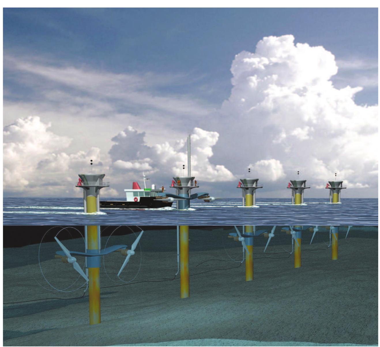
![FIGURE 3.39 Conceptual tidal current turbine used for tidal energy harvesting. EEE The power coefficient, Cp, is the percentage of power that the turbine can extract from the water flowing through the turbine. According to the studies carried out by Betz [18], the theoretical maximum amount of power that can be extracted from a fluid flow is about 59%, which is referred to the Betz limit. Tha thrict farce anniiaed tra the ratar can ho avnroccoed hry The thrust force applied to the rotor can be expressed by](https://figures.academia-assets.com/33302759/figure_214.jpg)


![FIGURE 3.53 PMSM vector control scheme. In ideal conditions, mathematical equations of vector control of PMSM can be expressed as PMSM can be actively controlled by vector control of rotor magnetic field orientation to get better torque characteristics. Figure 3.53 shows the vector control of a PMSM. PMSM is a synchronous machine with a rotor made of PM, so its vector control is much simpler than that of asynchronous machines [30]. Tn ideal conditions. mathematical equations of vector control of PMSM can be expressed as](https://figures.academia-assets.com/33302759/figure_228.jpg)

![The rotor winding is connected to the grid through “back-to-back” converters. A DC-link capacitor is placed, as energy storage, between these two converters to decrease the voltage ripple in the DC link. The machine side converter is used to control the torque or the speed of the DFIG and also the power factor at the stator terminals. The main objective for the grid side converter is to keep the DC-link voltage constant [26], as shown in Figure 3.56. Figure 3.57 presents one-phase equivalent circuit of the DFIG. FIGURE 3.57 Equivalent circuit of DFIG. (Modified from S. Tnani et al., “A generalized model for double fed induction machines,” IASTED Conference, 1995.)](https://figures.academia-assets.com/33302759/figure_230.jpg)


![Applying the chain rule [39], Equation 3.53 can be expressed by](https://figures.academia-assets.com/33302759/figure_238.jpg)


![In the case of any fault suchas under- or overvoltage of the grid, overcurrent or overheat of the power electronic devices, and undervoltage of the generator output, the grid-connected generation system may not detect the power outage immediately and self-cut from the grid [41]. As a result, the tidal current power generation system and near-by loads form a stand- alone island that is not fed by the grid [42]. In general, the islanding may harm the entire power system and the consumer side. Islanding affects voltage and frequency stability. It can also contribute to phase asynchrony. Therefore, detection of islanding by appropri- ate detection circuit is very essential for the tidal energy conversion systems. Figure 3.69 demonstrates an islanding detection system. ST ccs oll Be ee wee at ny Veeco eddicaceee Dee es Meow eee Ebest Vliet ain ond ccs TOT PF ec](https://figures.academia-assets.com/33302759/figure_244.jpg)

![decrease the amplitude and phase of the error. The summation of the corrected values of the given current and the current signal produced by the SPLL forms the reference current of the inner loop. Thus, the inner and outer loops cooperate to track the given current [41]. The reference point to produce the sinusoidal signal is provided by the zero-crossing of the grid voltage. Consequently, the SPLL is used to generate the given current in phase with the grid voltage. The control system block diagram is shown in Figure 3.71 [42], where Iyer is the reference current injected to the grid, Ipredicted is the predicted grid current, and Upredicted is the prediction of the grid voltage. a iy a. ae](https://figures.academia-assets.com/33302759/figure_246.jpg)


![FIGURE 4.15 Air-driven turbines using the wave power [14]. (a) Upcoming wave starts filling the chamber, (b) air is compressed by rising water, and (c) air is pulled back by retreating waves.](https://figures.academia-assets.com/33302759/figure_261.jpg)
![FIGURE 4.16 Falnes buoy-shaped wave-activated turbine. A wave contouring raft whose joints are formed by hydraulic pumps operating on the differential motions of the linked rafts as shown in Figure 4.18 was proposed by Wooley and Platts. The details of this method were discussed in Ref. [4]. This method has been experimented by Wavepower Ltd of Southampton, England. The individual rafts are built at a length of one-quarter of the wavelength of the waves that, on the average, contribute the greatest amount of energy. The rafts would be somewhat wider than their length in the direction of the advancing wave. scl Soe Aas | baad AS A. eorernlawalkla Avs. Be th ate alas lites tA. Ait Be ae Lames LA cise](https://figures.academia-assets.com/33302759/figure_262.jpg)


![where 9 is the air density, v is the mean axial flow velocity, Up is the circumferential velocity at mean radius (rg), b is the rotor blade height, | is the chord length, Ap is the total pressure drop between before and after the turbine, To is the output torque, and z is the number of rotor blades [25]. The Cy-® characteristics vary with respect to the different blade angles. The Cy value decreases if y increases in the stall-free region. This shows that the larger y results in better starting conditions. Besides, the stall point increases with y as well as the flow coefficient at no-load condition. The input coefficient Ca is higher at y = 0 than nonzero y values. This is caused by the rotor geometry. If y is different from zero, the Ca value is negative at small flow coefficients. This means that the rotor acts as a fan at smaller inlet angles. Thiic tha avaragcad narfarmancoa af tho rnatar aonac dawn wundaran ncrillating flaws can.](https://figures.academia-assets.com/33302759/figure_269.jpg)


![The turbine rotor with v = 0.7 hub-to-tip ratio is placed at the center of the test sec- tion. Then the turbine rotor is tested at a constant rotational speed under steady-state conditions. The performance of the turbine is evaluated in terms of the turbine angular speed, w, turbine output torque, To, flow rate, Q, and total pressure drop between the inside and outside of the air chamber, Ap. It should be noted that all of the turbines are self-starting [35].](https://figures.academia-assets.com/33302759/figure_274.jpg)


![FIGURE 4.30 Schematic of the air turbine-type wave power generator system. owever, it should be noted that efficiency is not the only important factor for optimal tur- dine selection in WEC. In addition, turbine characteristics vary with the efficiency of the air chamber, which is the ratio of the power of the OWC and the incident wave power [35]. Air- ‘low generated by the OWC is irregular due to the irregular natural behavior of ocean waves. hus, it is important to clarify the turbine characteristics under irregular flow conditions. The irregular test wave is based on The International Ship Structure Congress spectrum, which is specific for irregular wave behavior and is used typically in ocean applications [36]. AWEC system with an air turbine is presented in Figure 4.30, which shows the upcoming emi a ce cee ie ee eee Boe Ble oe oe Bae! eee es eee Ve Rage Coe le ae ee eee oe tle ce seeds Bile caste](https://figures.academia-assets.com/33302759/figure_277.jpg)


![FIGURE 4.36 Generator power. —— EE e—ee—e——e—eeeeeee ee The generator power and generator voltage are both in sinusoidal form as shown in Figures 4.36 and 4.37, respectively. The generator power has a biased sinusoidal waveform. In order to regulate the generator’s output power and voltage, the output of the linear generator terminals is first converted to the DC voltage and then filtered. Considering the large oscillations in the output, a large capacitor is required to achieve satisfactory voltage regulation performance. A boost DC-DC converter operating in the current control mode is employed, since the input voltage to boost the converter is the output voltage of the rectifier and that is fixed. Current control mode [38] helps optimum loading of the linear generator](https://figures.academia-assets.com/33302759/figure_284.jpg)


![FIGURE 4.44 Buoy power and output power versus current density. where f is the output frequency, p is the number of salient poles, and n is the rotation speed of the rotor shaft in rpm. Therefore, for a two salient pole machine, the synchronous speed would be 3600 rpm [48], since the output frequency of the system should be 60 Hz for grid connection. The armature excitation generates AC and this current is converted to DC so that armature exciter acts as a DC supply for field winding. The armature exciter has three phase windings in order to get the improved efficiency of three-phase rectification in comparison to single-phase rectification.](https://figures.academia-assets.com/33302759/figure_293.jpg)


![FIGURE 4.51 Flux density B versus field strength H. SLIGTIEVELIGLIRE UO LE] In the directly driven turbine topology, the active parts of the machine are surrounded by the periphery of the blades instead of placing them on the axis of the turbine as in the classical methods. This idea is studied in [50-52], which have presented successful results for marine propulsion. Some of those rim-driven propellers are used for autonomous underwater vehicles or vessel propulsion. A similar machine has been tested with a 50-W rating turbine in [49]. Ortltt ate, Pr eoe elect ait caer > nieaneents TEULG GALIM EYL PEs Some older technologies are based on the coupling of an axial flow turbine with an electric generator similar to wind turbines. A gearbox is required to shift up the typical rotor speed (10-20 rpm) to the speed of a conventional generator (above 500-1000 rpm). However, direct drive is an attractive solution to eliminate the complexity, failure rate, efficiency, and maintenance cost [49].](https://figures.academia-assets.com/33302759/figure_300.jpg)


![where B;, is the flux density remnant of the magnets, B is the ratio of magnet width to pole width (Lm/ Ipole), Rsm is the ratio of air gap diameter to magnet outer diameter (D/Dm), p is the number of pair poles, |r is the magnets relative recoil permeability, Mm and hg are the magnet and air gap heights, respectively. The slotless machine equivalent can be obtained by Carter factor [55]. Carter factor is a parameter to include the slotting effect on the air gap flux. If By, p, and Rsm are known hp can be solved to calculate the required magnet height. The slot height, hs, can be calculated as follows for a given loading current Ar, [54]:](https://figures.academia-assets.com/33302759/figure_303.jpg)


![The output of the induction generator is in the form of three-phase AC. The voltage can be controlled to maintain constant output voltage by adjusting the excitation current [59,60]. Thus, the output voltage can be fixed regardless of the load current and speed variations. A controller can be employed to determine the magnitude and frequency of the excitation current. The excitation current should be supplied to the stationary windings from which it is induced into the short circuited rotor windings. i a en, a i a: ee: i : en: en: ee ci: an, Laer In an induction machine, the synchronous speed and the angular velocity of the rotor can be expressed as](https://figures.academia-assets.com/33302759/figure_306.jpg)

![FIGURE 4.58 Linear switched reluctance machine cross-sectional view. Instead of using linear generators or conventional rotating generators, piezoelectric/ electrostrictive materials can also be used for WEC applications. A new device named Energy Harvesting Eel (Eel) is developed by Taylor et al. [64] to convert mechanical energy of ocean waves into electricity for powering remotely located sensors or devices used for .3.5.7 Ocean Energy Conversion Using Piezoelectric/Electrostictive Materials](https://figures.academia-assets.com/33302759/figure_308.jpg)


![FIGURE 4.61 Switched resonant power converter. impractical for use in Hel. The switched resonant-power conversion technique is used for electrical power extraction from the polymers. Using electrical and mechanical resonant systems, we can overcome the low coupling factor k, = d3!(Y/e) when piezoelectric devices are used as power generators. Eel motion has a very low frequency such as 1-2 Hz, so direct electrical resonance is not practical, since it requires very large inductor values. Therefore, switched resonant power conversion may overcome this limitation. Using this conversion, this technique is capable of high-efficiency operation at the 1-2 Hz range using reasonable inductor values [64]. Figure 4.61 shows the circuit schematic of the switched resonant power converter used for Eel energy harvesting [64]. Tn thie circiiit Rv renrecente the dielectric loce recictance af the niezoelectric (PVIDB) Cr](https://figures.academia-assets.com/33302759/figure_311.jpg)
![FIGURE 4.62 The interface structure for induction generator-based wave energy converters. JULUIrtuiirv-e aaa co ) Ve Vea Pe Xi Qe Een MLtito aa ala SEMEL LLY ru VV L £44 CULE LO VA LA to different periods and heights of waves [67]. A typical grid connection interface for use with generator applications is presented ir Figure 4.63. Although using several units has an effect on obtaining better overall wave forms, further conditioning is necessary for grid connection. Several WEC units have outpu voltages with different amplitudes, frequencies, and phases. DC bus voltage variations car be lowered if many units are connected together. After the rectification stage, capacito. tanks should be placed for better suppression of the DC bus voltage variations. The capac itor bank acts as a short time energy buffer for the sustainability of energy transfer to the grid, if any of the units does not meet any incident wave for a short time. These capacitor: are also used for the determination of the neutral point and the output filter of the inverter The third stage consists of a six-pulse insulated gate bipolar transistor (IGBT) inverter. Thi: inverter should be controlled to synchronize the inverter output voltage with grid quanti ties such as voltage amplitude and frequency. The synchronization is generally providec](https://figures.academia-assets.com/33302759/figure_312.jpg)

![FIGURE 4.65 Energy buffer system using a hydraulic PTO system with induction generator. enerator [4]. 1Nis also acts aS a Mechanical energy Durter [Oo]. The schematic configuration of the hydraulic PTO system is shown in Figure 4.65. The iydraulic PTO is composed of a hydraulic piston, a high-pressure accumulator, and a iydraulic motor. The high-pressure accumulator smoothes the mechanical power fluctu- tions caused by the wave power absorbers; thus power input to the induction generator vill be smoother but may have more or less fluctuations. The electrical storage may help in moothing the residual power fluctuations [68]. However, it would be better to handle the :ower smoothing at the same conversion stage, if the dimensions and cost of the conversion nd storage would stay in a reasonable range. STATCOM could also be used as an electrical](https://figures.academia-assets.com/33302759/figure_314.jpg)

![FIGURE 4.66 Induction generator in series with a full converter as grid interface technology eee ee ee eee ny ee ON Ne Ne EEE EE — ee eee eee ene eee ee ee EE DC/AC converter for grid and generator stator windings connection points [73]. This converter connection is called back-to-back converter, which is in series with rotor windings and shunt on the grid wires. With the aid of the hydraulic smoothing stage, the generator speed does not change too much, so the converters have lower ratings in comparison to the full converter in series [73]. However, doubly fed topology is not suitable for direct drive. The rotor side converter is used to control the power output of the system and the voltage (or reactive power) measured at grid connection terminals. The grid side converter generates or absorbs the reactive power by regulating the voltage of the DC bus](https://figures.academia-assets.com/33302759/figure_316.jpg)
![capacitor [74]. In other words, the rotor side converter controls magnetizing current and electromagnetic torque, while the grid side converter is controlled similar to STATCOM control [72]. In this topology, the rating of the converter limits the range of the variable speed operation. So it does not have as much capability as the full converter in the active control. The larger control margins can be reached by increasing the converter ratings, which in turn increase the cost. Thus, the full converter provides more flexibility of control. The system performance can be the same as a fixed speed generator in a STATCOM [73]. This structure is very common in wind farms, and the same technology can be implemented](https://figures.academia-assets.com/33302759/figure_317.jpg)
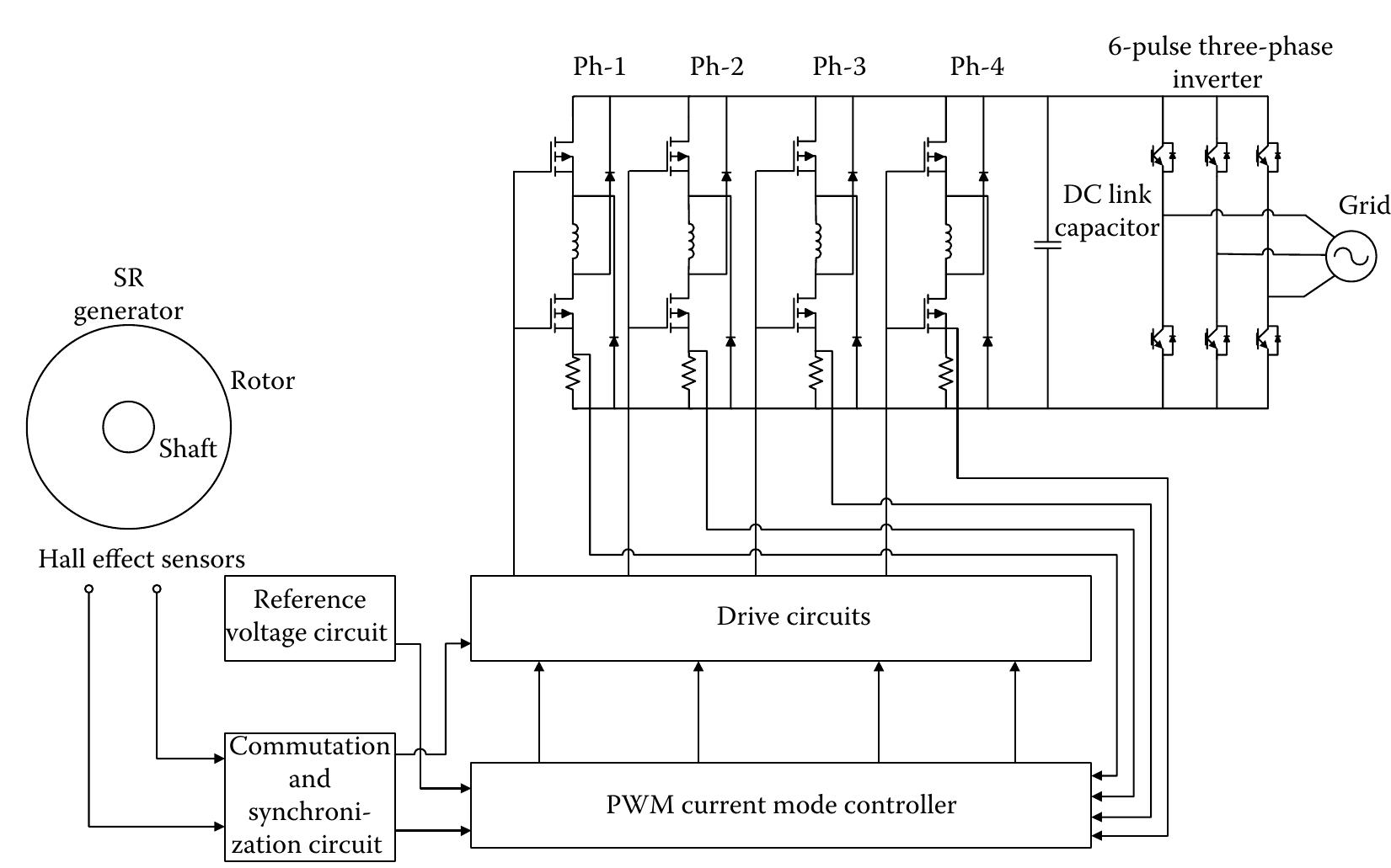
![FIGURE 4.68 Overall grid connection diagram of an SRG. An overall diagram of the grid connection interface for a SRG is given in Figure 4.68 [75]. The torque is a function of the angular position of the rotor due to the variable reluctance of SRGs. The phase currents of the SR generator should be controlled by the power electronic controller according to the certain positions of the rotor. In order to control the torque and transfer the available power to the grid, the magnitude and the waveform of the phase currents should be regulated by the power electronic interface. The safe operation of the](https://figures.academia-assets.com/33302759/figure_318.jpg)
![FIGURE 4.70 Block diagram of the operating principle of grid-connected SRG. power is first supplied from the capacitor, while transistors are conducting. The capacitor voltage turns at a point slightly before and after the aligned position. So, the bulk of the winding conduction period comes after the alignment. Current begins to rise while the rotor poles approach the stator poles of the next phase, which is going to be excited [77]. The phase current increases with extracting energy from the DC-link capacitor till the switches are turned off. The turn off event happens at the commutation angle, which is determined by the control circuit.](https://figures.academia-assets.com/33302759/figure_319.jpg)


![FIGURE 4.74 Electrical interconnection of Demo-Plant—in Oregon. (Redrawn from O. Siddiqui and R. Bedard. “Feasibility assessment of offshore wave and tidal current power production: A collaborative public/private partnership (Paper: 05GM0538),” EPRIsolutions, CA, Proceedings of the IEEE Power Engineering Society 2005 Meeting Panel Session, June 2005.) nO As shown i in Figure 4. 74, the commercial system uses a total of four clusters, each one ontaining 45 Pelamis units (i.e., 180 total Pelamis WEC devices), connected to subsea cables. iach cluster consists of three rows with 15 devices per row. The other state designs are ganized in a similar manner with four clusters. The number of devices per cluster varies uch that each plant produces an annual energy output of 300,000 MWh/yr. The four subsez ables connect the clusters to shore as shown in Figure 4.75. The electrical interconnection ot he devices is accomplished with flexible jumper cables, connecting the units in mid-water ‘he introduction of four independent subsea cables and the interconnection on the surface srovide some redundancy in the wave farm arrangement [2]. Pelamis was used to establish the cost model for a commercial scale (300,000 MWh/yr) ATANTYTA Laan T axgaliwad crAct rAMmMNnnANnaNnte aro ehnurmn in Biowroa A WE. T7Q] Tha caAct hveoa-daurnr](https://figures.academia-assets.com/33302759/figure_323.jpg)


![FIGURE 4.77 Operating principle of the Wave Dragon; waves overtop the ramp, water stored in a reservoir above the sea level and hydro turbines rotate as the water discharges. Teamwork Technology located in the Netherlands is the developer company of the AWS, which is an offshore submerged device. The device is activated by the oscillations of static pressure caused by the surface waves. Figure 4.80 shows the operating principle of the AWS [80].](https://figures.academia-assets.com/33302759/figure_327.jpg)
![The AWS is an air-filled cylinder of which the floater is a body heaving up and down to or from the fixed bottom part. The waves create a pressure difference on the top of the device resulting in the force that moves the active part of the device. High water pressure causes the chamber volume to reduce if the wave crest is above the AWS. The floater heaves due to the action of the chamber pressure if the trough is above. Here “trough” represents the concave between the two wave crests. The behavior of the air in the chamber is similar to a spring with a variable stiffness by pumping water in or out of the chamber [80,91]. PM linear synchronous machines are used within the AWS applications as direct drive energy conversion devices. Using an auxiliary energy storage or conditioning, the efficiency of this type of energy conversion can be improved.](https://figures.academia-assets.com/33302759/figure_328.jpg)

![The water dampers used within the AWS are actuated when the floating part approaches the mechanical end-stops. These dampers reduce the velocity of the floater and avoid the strong collision. Water dampers are also actuated with the electric generator when the floater does not have enough force required for adequate control of the movement of the AWS [91].](https://figures.academia-assets.com/33302759/figure_330.jpg)


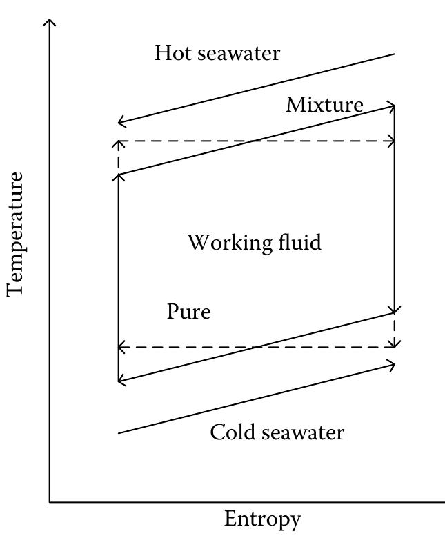
![FIGURE 5.11 Block diagram of open cycle. In an open-cycle OTEC process, which is shown in Figure 5.11, seawater functions as the working fluid. The boiling temperature of water is a function of pressure [13]. It drops as the pressure decreases. The first step is boiling the warm shallow water by placing it in a low-pressure container of about 2% atmospheric pressure at sea level. Then the expanding steam drives a low-pressure turbine coupled to an electrical generator. The 5.3.3.1 Structure and Principles of Open-Cycle Systems](https://figures.academia-assets.com/33302759/figure_344.jpg)


![into the U-type tubes, absorbing heat from the outside heat source (passing warm seawater), which will turn it to gas. Witch Wilt TUrTL It tO eds. In an evaporator, the main heat transfer passage is conduction, not the radiation or convec- tion. The conduction heat transfer can be defined as the transfer of thermal energy through direct molecular interaction within a medium or between mediums in direct physical contact without the flow of the medium material. The rate af heat trancfer can he eyvnrecced hu Newton’e canglinge law [320 21]: The rate of heat transfer can be expressed by Newton’s cooling law [30,31]:](https://figures.academia-assets.com/33302759/figure_348.jpg)


![FIGURE 5.22 Block diagram of the OTEC system controller. Heat quantity is used as the state variable for the upper control system of the OTEC sys- tem since it is more robust to the pressure and flow rate variations [37]. If the temperature is chosen as the state variable, the overall system becomes more complicated, since the temperature is very sensitive to the pressure and mass flow rate. Moreover, using the heat quantity as the state variable, highly nonlinear relationship between enthalpy and temper- ature /pressure can be eliminated. The power generation of the OTEC system is a function of the heat quantity difference between turbine inlet and turbine outlet working fluids. Therefore, the power generation can be controlled by controlling the heat quantity instead of temperature, because electric power can be calculated directly using the heat quantity. The nonlinear separation controller can easily be implemented in the OTEC systems and it is simplerin compare to other controller strategies based on the physical models [37—40]. The](https://figures.academia-assets.com/33302759/figure_354.jpg)


![FIGURE 5.25 Steam turbine speed governing system. Similar to the hydraulic turbine control, the main duty of the governor is to control the gate opening. A controller consists of a speed governor, a speed relay, a servomotor, and governor-controlled valves can be used to control the steam turbine [41]. The speed control system of a steam turbine is shown in Figure 5.25. i en nS a a ee ee, ee ee Se ey ee, ey MO mee 2 Ree Ce eh aoe 2 es: (yf 5.6 Control of a Steam Turbine](https://figures.academia-assets.com/33302759/figure_357.jpg)


![FIGURE 5.37 Multipurpose applications of OTEC systems. Deep seawater discharged from an OTEC plant contains high concentrations of nutrients that are depleted in surface waters due to biological consumption, and it is relatively free of pathogens. This is an excellent medium for growing phytoplanktons (microalgae), such as Spirulina, a health food supplement, and a variety of commercially valuable fish and shellfishes, such as salmon and lobster, which thrive in the nutrient-rich, cold seawater [45]. Suitable mixing of the warm and cold water discharges in various ratios can provide](https://figures.academia-assets.com/33302759/figure_369.jpg)