Anssi Laaksonen
580 California St., Suite 400
San Francisco, CA, 94104
2011
Anssi Laaksonen: Structural Behaviour of Long Concrete Integral Bridges 204 p. + 61 p. app. There are more than 20,000 bridges in Finland, of which about 2000 with a sum of span lengths over 20m are actual integral abutment road bridges. The lower building and maintenance costs of integral abutment bridges compared to conventional abutment bridges have increased interest for the former. This study deals with the structural behaviour of long concrete integral abutment bridges. The bridge subtype was limited to fully integral abutment bridges without any bearings or expansion joints. This study examines structural behaviour from the viewpoint of a bridge designer taking into consideration the effects of soil-structure interaction. It is a part of larger research project called "Soil-Bridge Structure Interaction". The main goal was to determine the effects of different soil properties at opposite bridge ends on the structural behaviour of fully integral bridges Another important goal was to determine the maximum allowable total thermal expansion length of a fully integral concrete bridge in terms of structural behaviour of piles at the bridge ends at the climatic conditions of monitored bridges. A further goal was to give suggestions for constructing integral bridges together with the whole research team. Three bridges, Haavistonjoki Bridge, Myllypuro Overpass and Tekemäjärvenoja Bridge, were monitored during this study. The main focus of the monitoring was the Haavistonjoki Bridge. The instrumentation of Haavistonjoki Bridge on the Tampere-Jyväskylä highway was completed in autumn 2003. Monitoring data have been collected by a total of 191 gauges, of which 98 are still working seven years after the monitoring started. The instrumentation is used to measure longitudinal abutment movements, abutment rotations, earth pressure behind abutments, superstructure displacements, frost depth, air temperature, and temperature differences in superstructure and approach embankment. The method for calculating uniform bridge superstructure temperature based on ambient temperature was developed on the basis of monitoring results from the Haavistonjoki Bridge. The temperature was calculated backwards until 1959 with this method. Obtained results correlate very well with the temperature loads of Eurocode EN 1991-1-5. Structural analyses were run on single laterally loaded composite piles and a whole bridge structure using software based on the finite element method. The analyses on single com-8.3.


![Figure 1.3. (a) & (b) frame abutments, (c) embedded abutment, (d) bank pad abutment, (e) & (f) end screen abutments. Integral bridge abutment types according to [137]. not discussed here.](https://figures.academia-assets.com/103679042/figure_004.jpg)

![bridge monitoring projects form the core of this comprehensive research. abutment bridges was completed in 2006 [75]. A railway bridge oriented dissertation was](https://figures.academia-assets.com/103679042/figure_006.jpg)

![Figure 2.1. Lateral subgrade reaction of pile in cohesionless soil. Notations as in Paragraphs 2.2.4 and 6.3.4 [43, 79]. where strains exceed the yield point.](https://figures.academia-assets.com/103679042/figure_008.jpg)
![Figure 2.2. “Development of passive earth pressure of non-cohesive soils versus normalised wall displace- ment v/v,”[121].](https://figures.academia-assets.com/103679042/figure_009.jpg)
![‘igure 2.3. Superstructure temperature components [116]. Here, the temperature field is divided in four parts. The most significant part in terms of](https://figures.academia-assets.com/103679042/figure_010.jpg)
![Figure 2.4. Superstructure uniform temperature range Te min aNd Te max [°C] [116]. in [116] have to be used. The range of the superstructure uniform temperature is presented](https://figures.academia-assets.com/103679042/figure_011.jpg)
![integral bridges. Figure 2.5 presents a stub-type abutment according to [2]. or an abutment will be 0.05 m [140]. The suggested limit would lead to relatively lon;](https://figures.academia-assets.com/103679042/figure_012.jpg)
![Figure 2.6. HP pile orientations in US Practice [106]. 2.6 are oriented for the weak axis. Displacement of 1% of end screen height is required to reach full passive earth pressure](https://figures.academia-assets.com/103679042/figure_013.jpg)

![Figure 2.8. The allowable pile load for a fixed (on left) and a pinned (on right) head in dense sand when bending is about the weak axis. The steel grade yield stress is 50ksi = 345MPa. [94].](https://figures.academia-assets.com/103679042/figure_015.jpg)

![Figure 2.9. Environmental factors that affect bridge temperature according to [68].](https://figures.academia-assets.com/103679042/figure_016.jpg)
![bridge is smaller than that of a concrete bridge. Figure 2.10. Daily ambient air temperature in Fairbanks, Alaska, USA [68].](https://figures.academia-assets.com/103679042/figure_017.jpg)
![Figure 2.11. Effective bridge temperature (EBT) as a function of time. Seasonal and diurnal variations for bridge superstructure are shown [31]. In this dissertation EBT is the uniform temperature, Ty. superstructure. changes take a few days to develop due to the quite big specific heat capacity of a bridg uitable term than daily or diurnal fluctuation because significant uniform temperatur sented by certain fractiles which have a specific recurrence time according to presen](https://figures.academia-assets.com/103679042/figure_018.jpg)

![Figure 2.13. Earth pressure behind end screen as function of end screen displacement. Bridge No.203 [107]. smaller. The weekly and diurnal behaviour of earth pressure is also shown.](https://figures.academia-assets.com/103679042/figure_020.jpg)
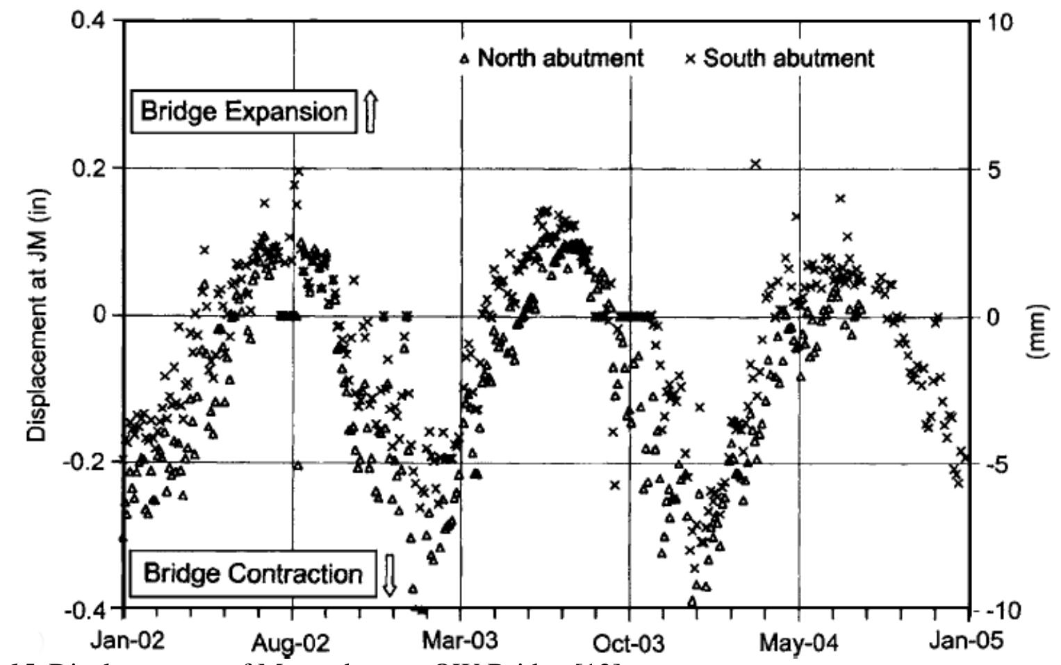
![thermal expansion length is 83.7 m. JS state of Massachusetts was monitored from 2002 on [13]. The composite bridge's total](https://figures.academia-assets.com/103679042/figure_021.jpg)

![the embankment which allows a small displacement to cause high earth pressure [58]. Figure 2.17. Earth pressure behind abutment in Scotch Road Bridge [58]. high. Yet, the highest earth pressure was measured in winter. This is due to the freezing of](https://figures.academia-assets.com/103679042/figure_024.jpg)
![Figure 2.18. Average bending moments of supporting piles of Scotch Road Bridge in June-July. The values were calculated by the LPILE program. [59]. moments of the supporting piles in June-July are presented in Figure 2.18. The bending moments are distributed along the pile length. The biggest bending moments](https://figures.academia-assets.com/103679042/figure_025.jpg)

![Aug-96 Aug-99 Aug-02 Aug-05 Aug-08 Aug-11 Aug-14 Aug-17 Aug-20 Aug-23 Aug-26 Figure 2.21. Tendencies of computed and measured pile curvatures [66].](https://figures.academia-assets.com/103679042/figure_028.jpg)

![Figure 2.23. Idealised strain on supporting piles as function of time ina fully integral bridge [3, 26]. tegral abutment is presented in Figure 2.23 [3, 26].](https://figures.academia-assets.com/103679042/figure_030.jpg)


![By introducing a dimensionless variable, written [133, 104]: ited along depth (see Figure 6.18a) and q = 0, the following differential equation can be](https://figures.academia-assets.com/103679042/figure_032.jpg)
![Figure. 2.25. Power functions of modulus of lateral subgrade reaction [95]. soils are presented in Figure 2.25. Power functions and distributions of modulus of lateral subgrade reaction in cohesionles: 141]. The solutions require series development. Solutions for cases where the modulus of](https://figures.academia-assets.com/103679042/figure_033.jpg)
![Figure 2.26. Comparison of moment values of different distributions of modulus of lateral subgrade reaction [95]. Pile has hinged top connection. Loading is a lateral force on top of pile. On the left, unitless moment values; on the right, distributions of modulus of lateral subgrade reaction. distributions of the modulus of lateral subgrade reaction are presented in Figure 2.26.](https://figures.academia-assets.com/103679042/figure_034.jpg)
![Figure 2.27. Force-displacement relationship of pile-soil-interaction, for terms see Formula 2.25 [20]. reaction is presented in Figure 2.27. infinite length. A general hyperbolic force-displacement relationship of lateral subgrade stiffness and ultimate resistance affect the force-displacement relationship along different](https://figures.academia-assets.com/103679042/figure_035.jpg)
![Figure 2.28. Hyperbolic stress— strain relationship with scaling parameter Ry. The figure is based on [123] [he hyperbolic stress-strain relationship with scaling parameter R¢ is presented in Figure](https://figures.academia-assets.com/103679042/figure_036.jpg)
![Figure 2.29. Influence of Pile Diameter on Dimensions of Bulb Pressure [129]. presented in Figure 2.29. aviour has been continuum bulb pressure. That pressure at two different pile diameters is](https://figures.academia-assets.com/103679042/figure_037.jpg)
![Figure 2.30. Distribution of front earth pressure and side shear around pile subjected to lateral load [125].](https://figures.academia-assets.com/103679042/figure_038.jpg)
![Figure 2.31. Effect of pile cross section on q-y curve [9]. Loose sand ¢ = 30° and dense sand od = 40°. [75]. The shape of the pile cross section also affects lateral behaviour [9].](https://figures.academia-assets.com/103679042/figure_039.jpg)
![Figure 2.32. Hysteretic backbone curve [130].](https://figures.academia-assets.com/103679042/figure_040.jpg)

![Figure 2.34. a) Soil-pile superstructure model b) variation in q-y curves along depth [97].](https://figures.academia-assets.com/103679042/figure_042.jpg)
![elasto-plastic springs in [97], see Figure 2.35. The solution consists of several springs connected to the same node. The method allows](https://figures.academia-assets.com/103679042/figure_043.jpg)

![Figure 2.37. Hysteresis loops of q-y with components of different pile sides [4]. teresis loops of different sides of a pile are presented in Figure 2.37.](https://figures.academia-assets.com/103679042/figure_045.jpg)
![Figure 2.38. Effect of fully integral bridge end rotations on pile curvatures [66]. piles, see Figure 2.38. rotations. Rotation of the bridge end screen decreases the curvature of the top of supporting](https://figures.academia-assets.com/103679042/figure_046.jpg)
![Figure 2.39. Soil-structure interaction behaviour of a single-span fully integral bridge under live load [29]. tion, and the superstructure is displaced under the live load.](https://figures.academia-assets.com/103679042/figure_047.jpg)
![Figure 2.40. Soil-structure interaction behaviour of a three-span integral bridge under live load [27].](https://figures.academia-assets.com/103679042/figure_048.jpg)
![Figure 2.41, Massachusetts OW Bridge abutment and approach slab details [22]. porting piles are subjected to smaller strains from temperature and live loads. tion of a predrilled hole is to reduce the modulus of lateral subgrade reaction when sup-](https://figures.academia-assets.com/103679042/figure_049.jpg)
![Figure 2.42. Calculated effects of predrilled holes on pile curvature at falling uniform temperature 27.8°C for the 66.9 m total expansion length. On the left stiff clay, on the right very stiff clay [66].](https://figures.academia-assets.com/103679042/figure_050.jpg)
![2.43 [66]. Here, the pile head is treated as a partly hinged connection with limited hinge](https://figures.academia-assets.com/103679042/figure_051.jpg)
![Figure 2.44. Abutment with hinged support at top of pile [25].](https://figures.academia-assets.com/103679042/figure_052.jpg)


![of end screen displacement gauges are presented in Figure 4.3. TUT so that they measured earth pressures accurately and were durable [84]. The locations sliding gauges during check surveys. The devices are placed so that end screen rotation](https://figures.academia-assets.com/103679042/figure_055.jpg)


![Figure 5.26. Speed of loading vehicle, change of earth pressure between end screen and embankment at EPC K and displacement of superstructure at measurement location 10 of abutment T4 in the braking test. and the 500 KN braking force for this type of bridge was given in the guidelines [42]. The braking force induced a longitudinal displacement in the superstructure against abut- The developed force was rather significant compared to the mass of the loading vehicle,](https://figures.academia-assets.com/103679042/figure_092.jpg)


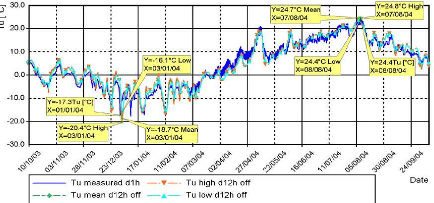
![Table 5.2. Calculated and measured extreme Ty values during the four-year monitoring period [°C]. Monitor- ing year changes on 10" of October. *) Compared at time when monitoring devices were measuring properly and Ty was not at its lowest.](https://figures.academia-assets.com/103679042/table_005.jpg)


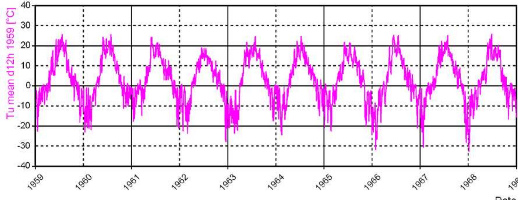
![Figure 5.41. Calculated annual extreme values of Ty from 1959 to 2007 as function of annual extreme values of ambient air temperature and Ty values according to Eurocode [102].](https://figures.academia-assets.com/103679042/figure_107.jpg)

![Figure 5.43. Earth pressure-displacement relation between end screen and embankment as measured and presented in Finnish guidelines [46].](https://figures.academia-assets.com/103679042/figure_109.jpg)


![Figure 6.4. Strain stages for capacity calculations of composite pile cross section. Strain unit is [%o]. Tension is positive. -2 %o and -3.5 %o at the edge of the cross section with normal strength (fex.cube < 60 MN/m‘’)](https://figures.academia-assets.com/103679042/figure_113.jpg)


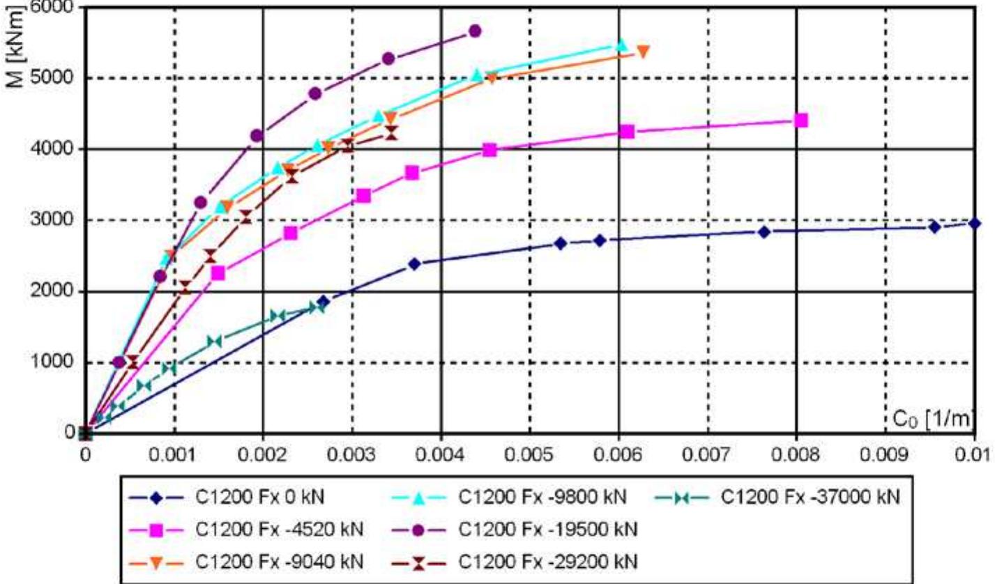
![*) Cross section dimensions in Finnish manufacturing are D*t = 1219*16 Table 6.2. Composite cross section capacity with component N [kN] and M [kNm] No,opt2 18 calculated with the simplified formula:](https://figures.academia-assets.com/103679042/table_007.jpg)


![behaviour. Four different types of distribution are presented in Figure 6.18. Figure 6.18 a)-d) Linear, constant, parabolically distributed modulus of lateral subgrade reaction according to Finnish guidelines [43]. In the Figure the pile is rotationally supported from the top of pile. The distribution of modulus of lateral subgrade reaction affects the laterally loaded pile](https://figures.academia-assets.com/103679042/figure_127.jpg)

![Table 6.5. Distances s [m], according to Figures 6.18 and 6.19 moment develops at the top of pile:](https://figures.academia-assets.com/103679042/table_010.jpg)


![Table 6.6. Displacement capacities [m] of yjop at Do with Nop: in T1_R- and T2_Rmodels](https://figures.academia-assets.com/103679042/table_011.jpg)


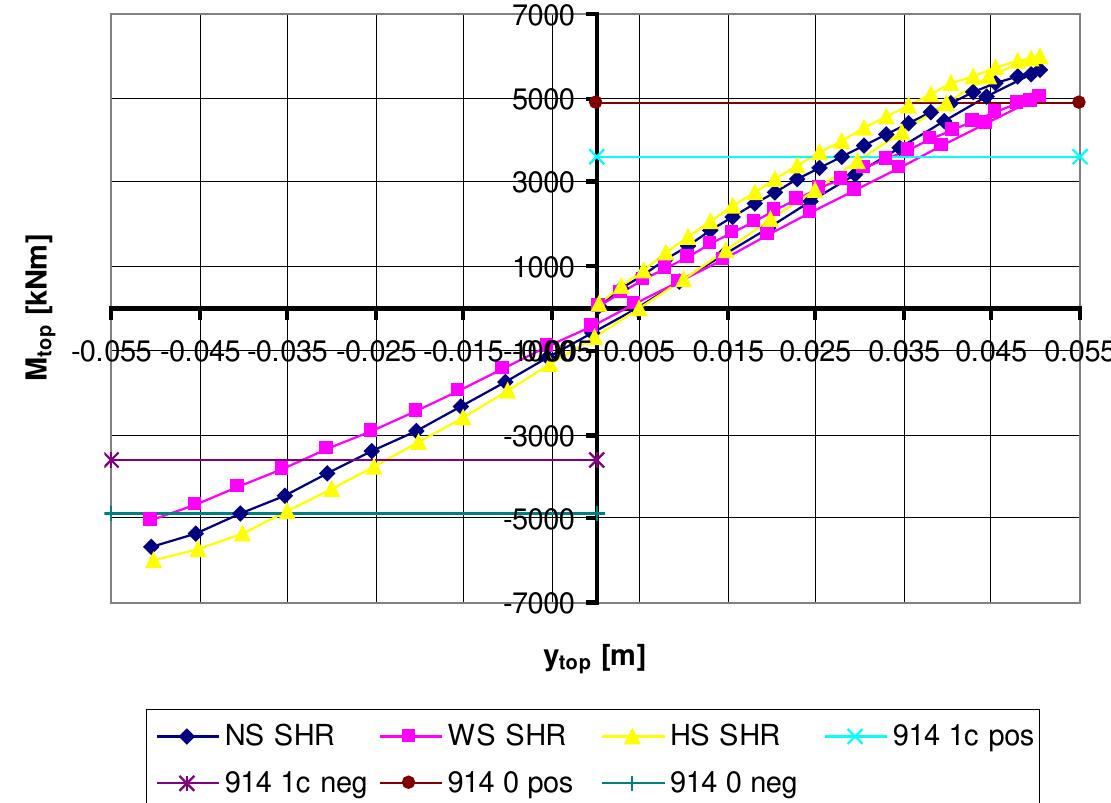
![are presented in Figure 6.36. composite cross section), Table 6.5 (values of s) and Table 6.6 (displacement capacity of length in the EXP models are higher than in the SHR models and in the T2 than in the T]](https://figures.academia-assets.com/103679042/figure_145.jpg)
![Table 6.7. Equivalent modified constant of lateral subgrade reaction m,-, when modulus of subgrade reactior is linearly distributed along pile length [MN/m°] Values Of Mheq are almost independent of pile diameter in terms of bending moments partly](https://figures.academia-assets.com/103679042/table_012.jpg)

![Table 6.8. The selection of structural heights ha was based on existing bridges and reference [37]. Th](https://figures.academia-assets.com/103679042/table_013.jpg)


![Figure 6.41. Balancing of uniform load, in the figure: Fy, = Fy, [90, 91]. slightly upwards. This kind of load-balancing method is presented in [90, 91]. of spans from combined displacement from permanent load and post-tensioning force was](https://figures.academia-assets.com/103679042/figure_150.jpg)


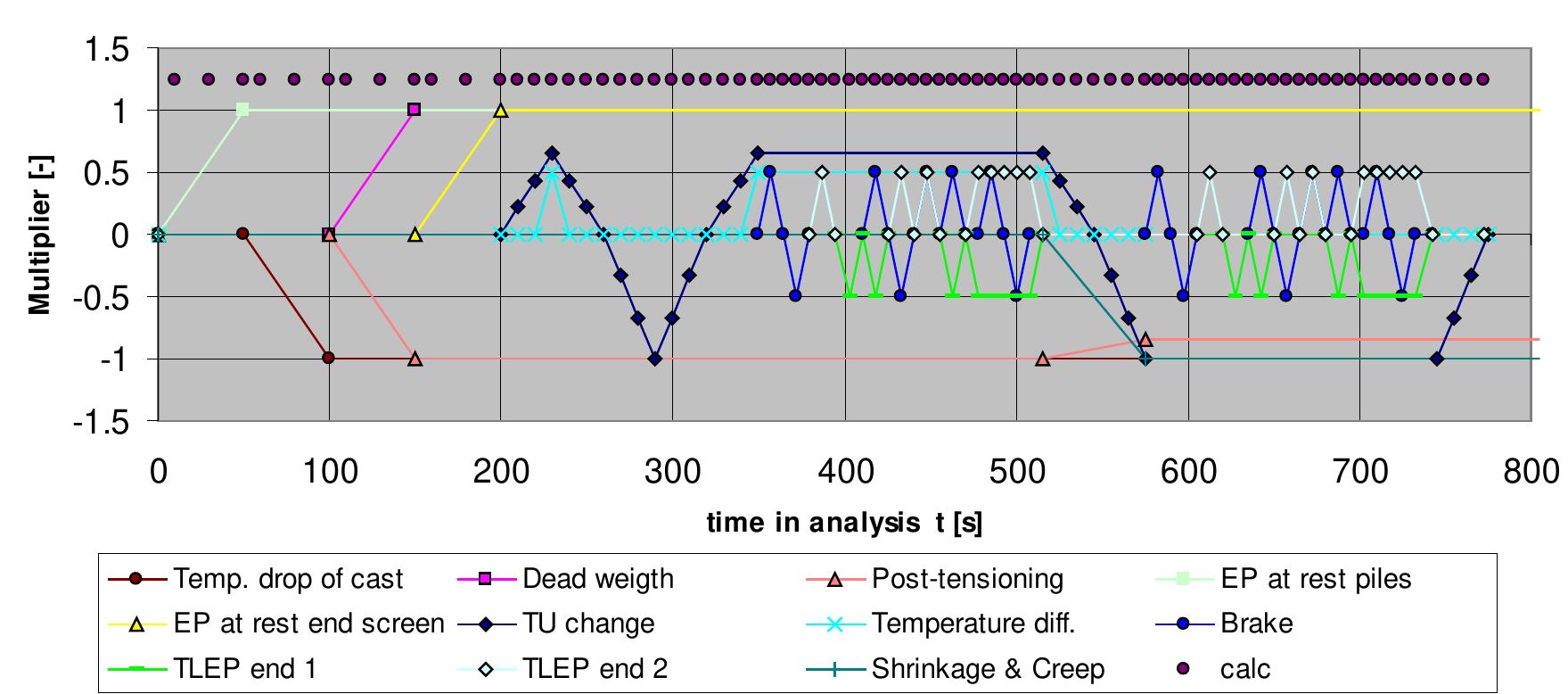
![Table 6.12. Strains and equivalent temperature drops The shrinkage strain €¢ snr of concrete is set to -0.00025 [-] [35, 45]. Then the equivalen perature drop values and corresponding strains are presented in Table 6.12. drop ATmoa, which is the equivalent temperature drop AT.g multiplied with mg. The tem- has been applied. The discussed loads were assigned to the FE model with temperatur](https://figures.academia-assets.com/103679042/table_017.jpg)